Considerations
Before beginning I should mention some assumptions that I made beforehand. I will assume that you have a decent understanding of programming a PIC in assembly language and therefore I won't spend time going over the basics of configuring every single peripheral and some of the more basic subroutines found in the programs (delays etc...). More info on AD conversions can be found in my H-Bridge tutorial as well as the very informative Googlium Tutorials
Initialization
Upon processor startup, you will see a call to "peripheralInit":
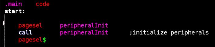
The subroutine "peripheralInit" is found in the init.asm file and contains all of the necessary startup code to configure microcontroller pins and peripherals as well as the 20x4 LCD panel of the control box. Additionally, the LCD displays a message to the user letting him know that the system is currently initializing.
After initializing the peripherals, a series of handshakes are performed between the ROV and the control box. At the time of writing this, the control box should be powered up before the ROV. This basically ensures that the MCUs on both devices are properly initialized before general communications are attempted. After a successful handshake with the ROV, the information headers are displayed to the Hitachi LCD screen and the "ESC ready LED is lit.
Main Loop
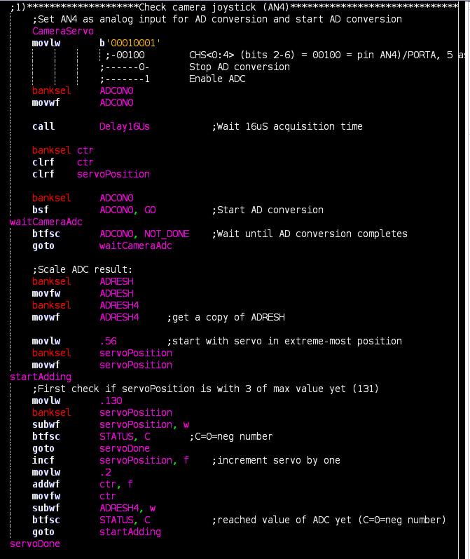
The main loop of the program begins by sampling the the seven analog inputs connected to the various joysticks and knobs. These inputs are responsible for controlling the speed and direction of the ROV as well as the on-board lights, camera and gripper arm. Each time the ADC module is configured to sample the appropriate input, the sample is performed, converted to a useful value and then saved away as a variable to be sent to the ROV later. Below we see all of this happening with the input connected to the camera control knob:
The process for converting the ROV control joystick into meaningful values is somewhat more complex as the ADC values need to be manipulated in a way the makes logical sense given the movement of the joystick.
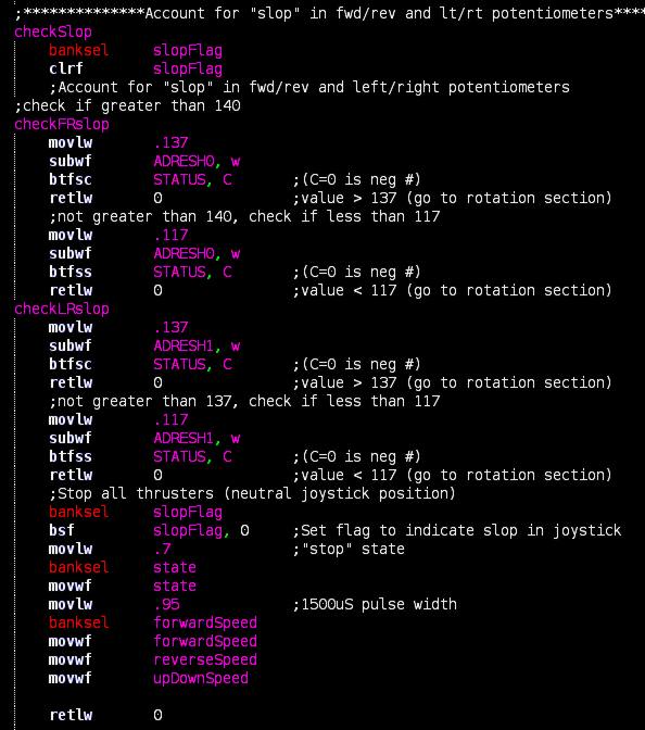
Additionally we need to take into account the play or "slop" of the joystick. Simply moving the control box around may induce small and unintended movements of the joystick. Also, depending on the quality of your joystick, it may not exactly hold to true "dead center" when released to a neutral position. I make a call to the subroutine "checkSlop" to handle this:
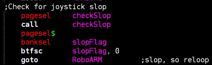
The contents of the subroutine are as follows and can be found in the motorCalculations.asm file:
"State"
In the course of processing analog values for the ROV control joystick, the "state" variable is used to signify the overall intended direction of movement for the ROV and can be one of 8 numbers.. This comes into play when we transmit or UART data packets and the ROV MCU parses out the data packets. For now just know that the state codes can be found in the UART State Codes document and are described below:
- 0 = Forward
- 1 = Reverse
- 2 = Traverse Right
- 3 = Traverse Left
- 4 = Rotate Clockwise
- 5 = Rotate Counter Clockwise
- 6 = Up/Down
- 7 = Stop
So with that completed we have finished the main loop of the programs and achieved movement along the x and y axes. We have yet to discuss movement along the z-axis (diving and surfacing) or rotation about the z-axis (clockwise and counter-clockwise rotation). To accomplish those things we will turn to interrupts in the next section.