
So we left off last time mentioning the need for a device to drive our MOSFET switches. Generally speaking, a MOSFET needs about 10v above the ground reference in order to switch the device on. As usual, this can vary with each device so it's best to consult the data sheet to be sure. Our two P-Channel MOSFETS on the "high side" of the H-bridge will have their gate pins connected to the 12 volts of the motor circuit to keep them turned off until we want them on (at which time we will ground the gate pin). On the other hand, our N-Channel MOSFETS on the low side of the h-bridge will have their gate pins connected to ground to keep them in a default state of "OFF". To turn them on we will need to place 12v on their gate pins.
Although we haven't yet discussed the microcontroller we will be using to control our h-bridge, it is important to realize that it will be outputting a signal of 5v or 0v which represent on or off states for the MOSFET switches. As mentioned above, 5v isn't enough to switch our N-channel MOSFETS on. We need an intermediary device to convert each 5v signal to 12 volts. There are many MOSFET drivers available but I already had an H-bridge driver IC (integrated circuit) that allowed me to do just that.
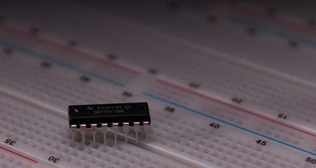
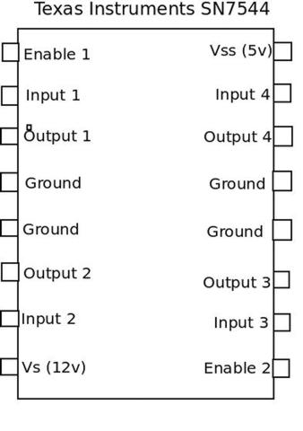
The above IC is a Texas Instruments SN754410 H-bridge driver ( Data Sheet )
This device can actually be used by itself to drive a small motor as it is essentially an H-bridge contained in a small integrated circuit. It's usefullness is limited however as it can only handle less than 1 Amp of current output. It doesn't take a very large DC motor to exceed this limit. On the other hand, the MOSFETS in our h-bridge can handle up to 27 Amps of continuous current output for the P-Channels and 30 Amps for the N-Channels. An h-bridge that you construct yourself will be able to handle a wider range of DC motors as opposed to the comparatively weak IC devices. So, rather than connecting it to the motor directly, we will use it to operate our MOSFET switches (which draw almost zero current).
We will revist this driver when we begin assembling our circuit but the connections are pretty straight forward. Enable pins are connected to 5v along with the logic supply voltage pin. Ground pins are grounded (there is a catch to this) and supply voltage from the motor circuit is connected to "Vs." The signals from the microcontroller will enter through the input pins of our driver and output will go to the corresponding gate pin of each MOSFET.
That about does it for the background info ouf our H-bridge. Let's now discuss the required components.