The purpose for constructing this vacuum chamber was to allow me to pot the windings of brushless motors (making them suitable for underwater use). The chamber itself consists of the container portion of a Harbor Freight pressure tank (used for painting). Below is a link to the unit:
The vacuum pump I used is a 2.5 CFM model (also from Harbor Freight):
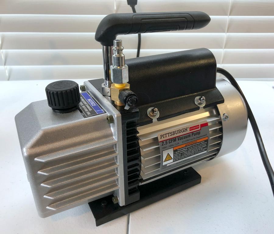
(Link to the Harbor Freight vacuum pump)
Constructing the lid
The lid that comes with the tank was not used. In its place I used a 1 inch thick piece of acrylic (plexigalss) sourced from a local plastic supply company. The transparent plexiglass allows you to monitor the effects of the vacuum environment on the piece being potted. The circular shape was traced out using the original lid as a template and cut with a jigsaw and carbide blade. In order to get a good seal between the lid and the tank, a channel was routed out in the plexiglass. This allows for the use of a gasket to achieve an airtight seal. The diameter of the channel was determined by tracing out the lip of the tank. The depth and width I went with were 6mm by 17mm respectively. The was cut made using a router and a straight bit:
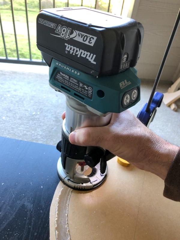
Acrylic is pretty hard stuff, so multiple passes were made until the desired depth and width of the channel were achieved.
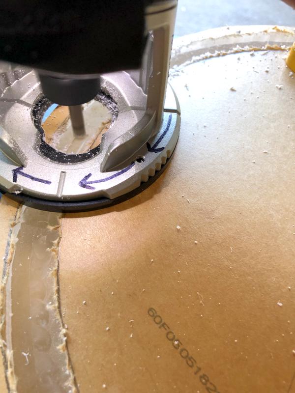
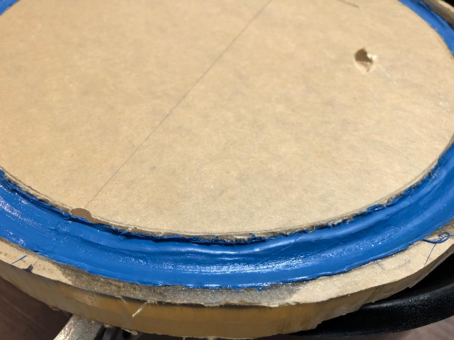
A circle cutting jig would give a more accurate/consistent width for the channel, but since I intentionally cut it wider than necessary, (to account for a gasket), such accuracy wasn't needed and the cut was made free-hand. The final result is shown below:
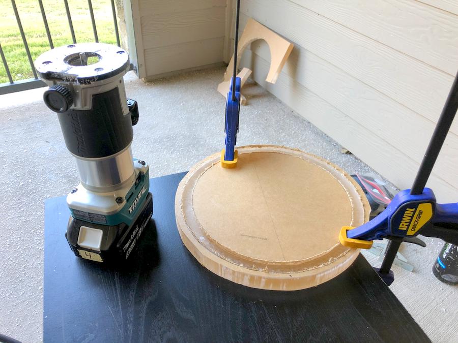
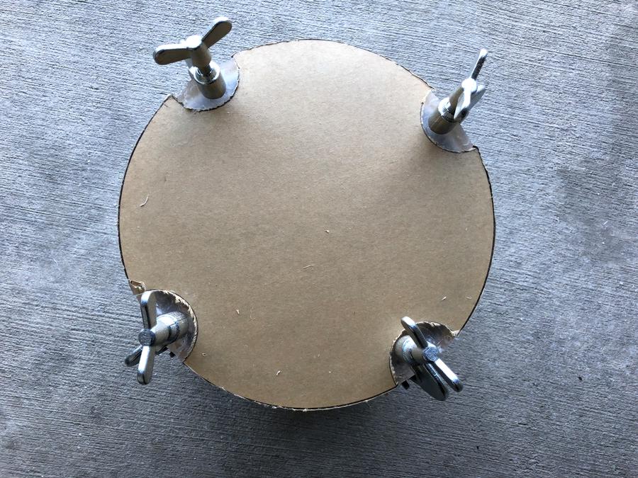
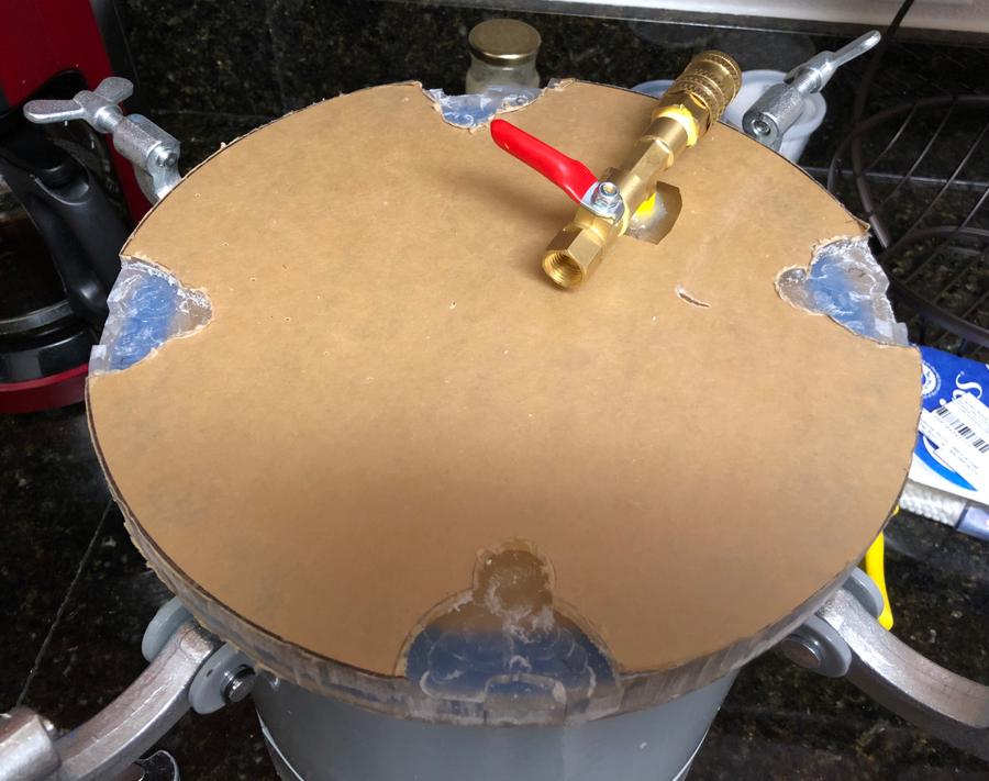
In the photo below, you can see some relief notches I cut out for the latches that hold the lid to the tank. These were completely unnecessary however as the gasket (described below) immediately created an air-tight seal without needing any extra downward pressure. After that, the vacuum effect will hold the lid in place.
Air-tight gasket:
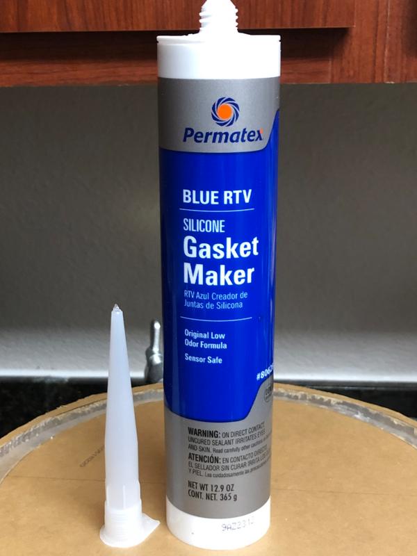
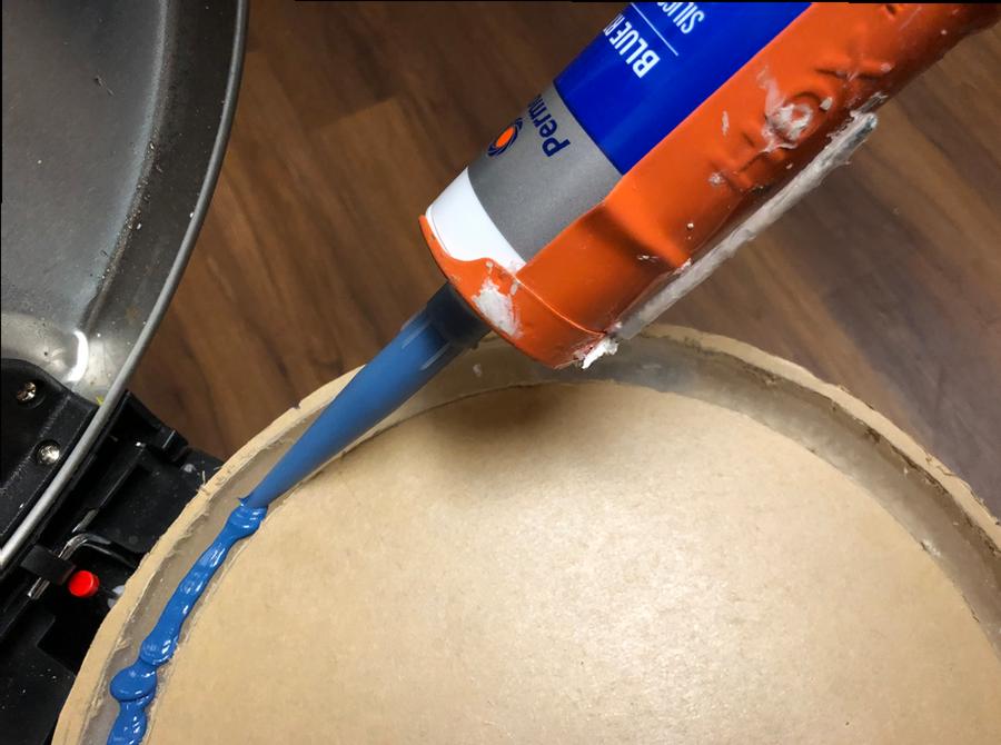
To make the gasket I used blue RTV:
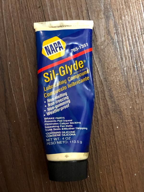
Silicon grease was used as a release agent during the forming/molding process:
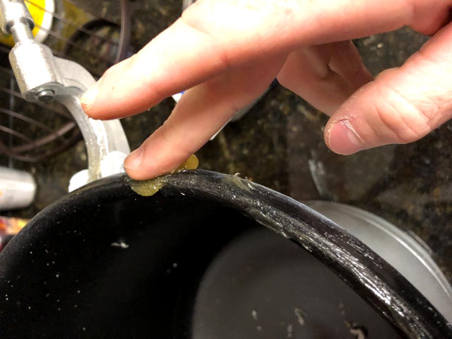
I started by smearing a liberal amount of silicon grease along the lip of the tank to prevent the wet RTV from adhering to it:
I then ran a bead of RTV along the inside of the channel.
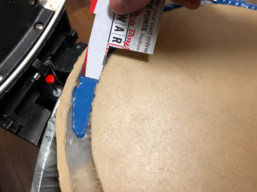
A cut up plastic card was used to smooth out the bead of RTV
Below we see the final result prior to forming the shape of the gasket. I used enough RTV to fill the channel about half way (in terms of its depth).
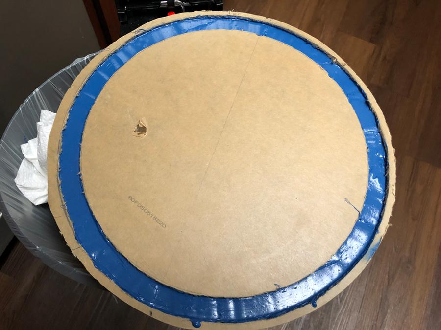
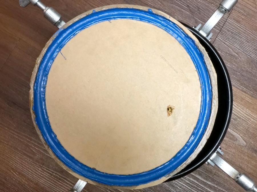
With the RTV still wet, I placed the lid on the tank and used light pressure to imprint the shape of the tank lip. Don't press so hard that you create hard contact between the lip of the tank and the plexiglass lid. After allowing the RTV to cure for 24 hours, I got the result shown below:
Fittings
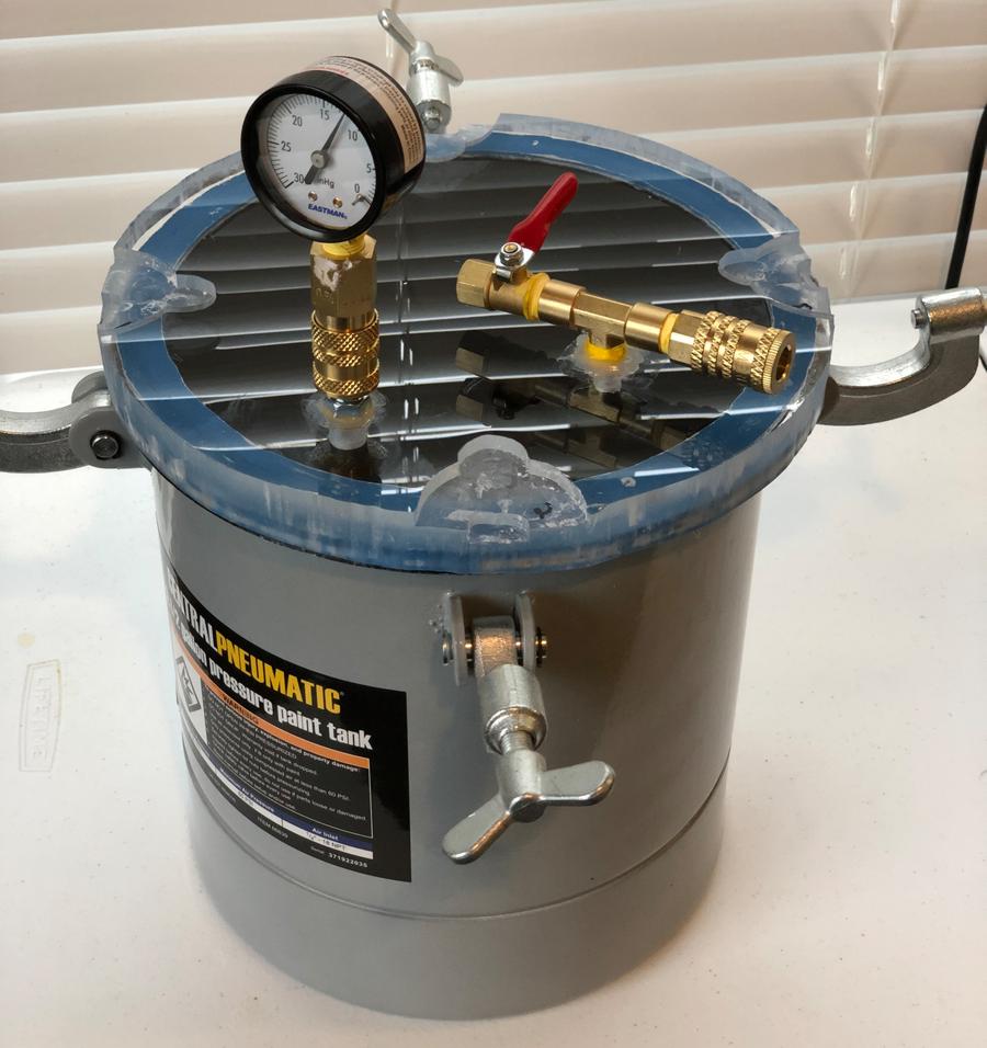
A hole for a "tee" fitting was drilled into the plexiglass lid. One end of the fitting is a female QD (Quick Disconnect) air line fitting that connects to the vacuum pump and the other end is a ball valve used to relieve/control the vacuum pressure. Ideally I would have tapped the hole to allow the fitting to be threaded in place. Since I didn't have any 1/4 inch NPT taps on hand, I just drilled the hole slightly under size and allowed the tee fitting to act in a "self-tapping" manner as I screwed it in. Clear silicon caulking and thread tape were used to ensure an airtight seal.
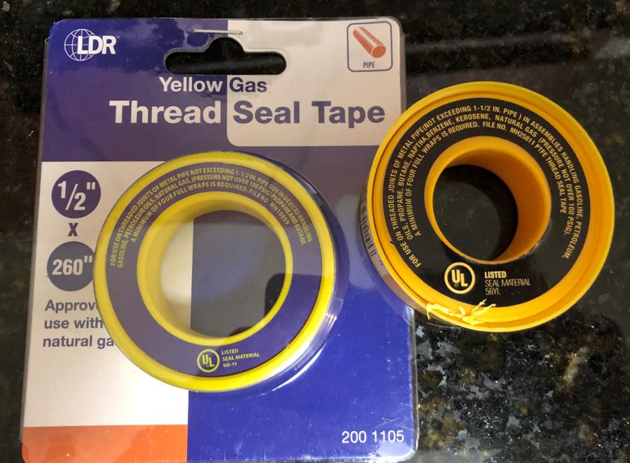
Yellow thread tape (rated for gas) was used on all fittings:
Finally, a vaccum gauge was added using QD connectors. I also used it to check for leaks in the gasket/fittings by applying a vacuum to the system and monitoring it for several hours with the pump disconnected. Unfortunately, the gauge I purchased from the local big box store was defective and had an inaccurate zero calibration. I was still able to use it by simply offsetting the reading by the amount of error displayed at "zero". Needless to say I plan on replacing it soon.
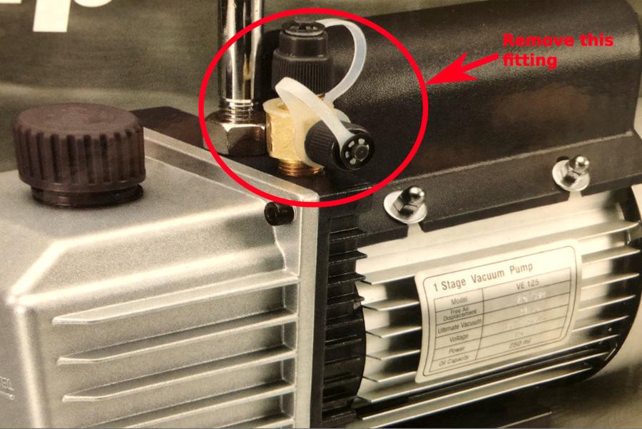
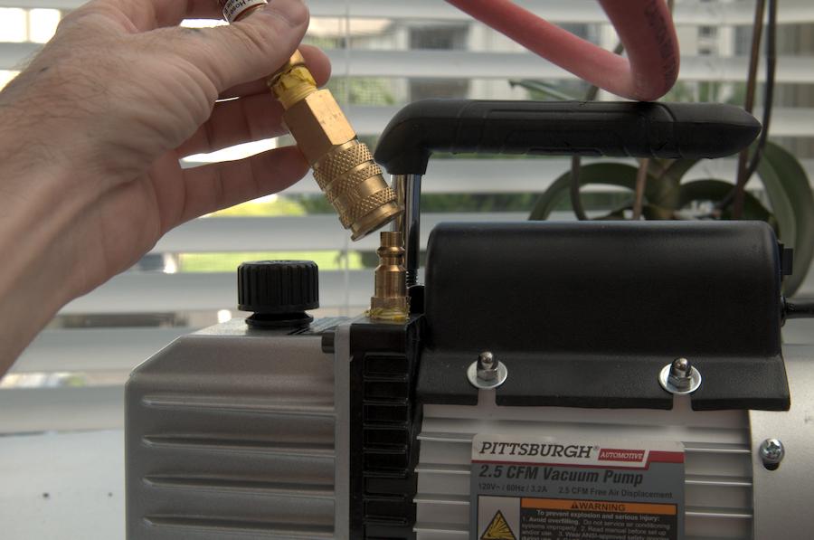
Since I planned on using QD fittings for all connections, I removed the fitting/plastic cap setup found on the Harbor Freight Pump and replaced it with a male 1/4 in air hose fitting. The threads were sealed at the factory with pipe dope which made it somewhat stubborn to remove. I found it necessary to remove the pump handle to provide clearance for a wrench.
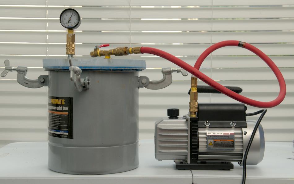
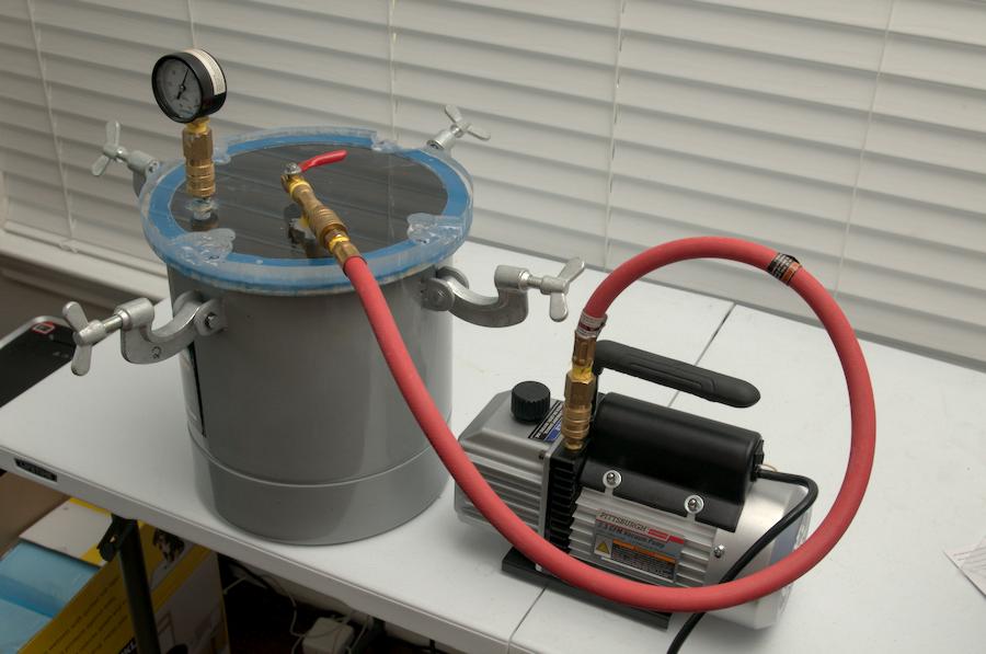
Afterwards I was able to connect the pump to the chamber in the manner shown below:
Side Note:
When using the Harbor Freight pump, it was necessary to disconnect the air line if I intended on leaving the tank under vacuum pressure for more than a few seconds.
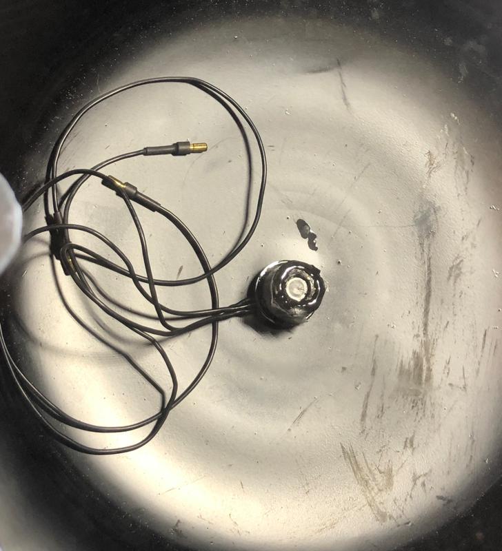
Whether the pump has bad seals or a faulty internal check valve, I found that lubricating oil would make its way into the air lines under sustained vacuum (not good). Nevertheless, the system works very well overall and allowed me to pot brushless motor windings by evacuating any air bubbles in the thermally conductive epoxy: