Overview and Goals:
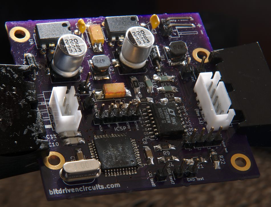
Our goal here is to design a Battery Monitoring Circuit (BMC) that can sample the voltage of the individual cells in a 4s LiPo battery such as the one found here. (also shown below:)

Our primary method of doing this will be through differential amplifiers connected to the 5-pin JST-XH connector of the battery. This connector is shown below:
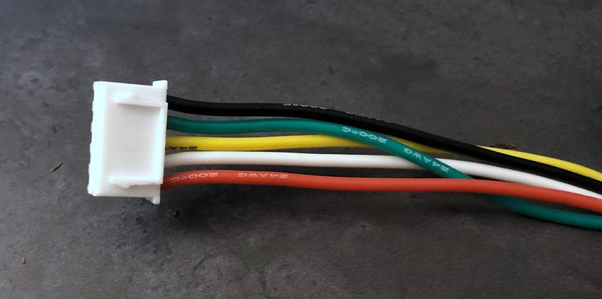
The black wire is connected to the negative terminal of cell #1 of the battery pack. This reference voltage will be connected to ground of the BMC. Using the battery shown above as an example, we see that the nominal voltage of the pack is 14.8 volts. This means that each cell (there are 4 cells in a 4S pack) will measure a nominal 3.7 volts. For purposes of illustration, if we assume that the pack is at its nominal voltage, the wires of the JST-XH connector will have the following voltages values (with respect to ground of our monitoring circuit):
- Black: 0 V
- Green: 3.7 V
- Yellow: 7.4 V
- White: 11.1 V
- Red: 14.8 V
From observation (and by measuring the voltages of each cell with respect to the black wire) you will notice that the individual cells are connected in series. Our sampling technique wil involve using differential amplifiers (configured as subtractors) to measure the difference in voltage levels between each wire of the connector and the wire that proceeds it (in order of the series connection). The resulting output of these differences will be sent to 4 analog input pins of a PIC microcontroller and measured against a reference voltage of 4.2V (4.2V is the maximum cell voltage for LiPo batteries). For LiPo battery chemistry, it is important to not allow any individual cell to drop below 3.0 per cell (for both battery life and safety reasons). Therefore the microcontroller ADC results from each cell will be scaled to reflect a range of values from 3.0-4.2 V.
Communication between battery monitor and external MCU:
Once the cell voltages are determined by the BMC, they will be read by external devices via the i2c protocol. This process is interrupt driven and triggered by an i2c "START" condition sent by the external device. In this project, an additional program is written for a separate PIC MCU to simulate the requesting of battery data from the BMC.
In the next page, we will examine the contruction and components of the circuit.
Continue on to Battery Monitoring Circuit components and layout.