All documentation on this page references the program file for the Battery Monitoring Circuit (BMC) named batMonMain.asm.
I2C communication between master and BMC slave
Configuring the I2C module
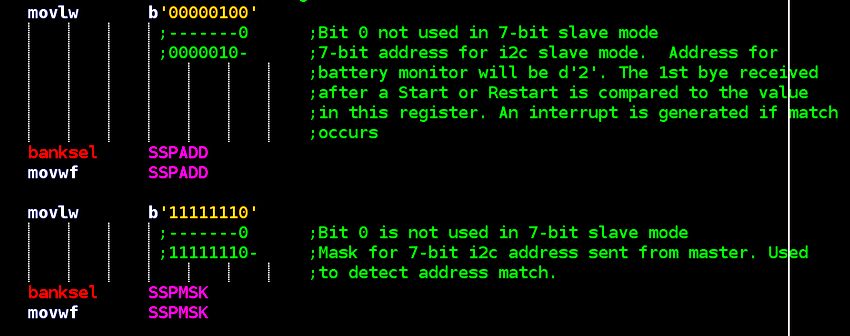
As was mentioned at the beginning of this project documentation, the sampling of the 4 battery cells is interrupt driven. With the PIC16F1937, we can configure the device in a manner that causes an interrupt to be triggered upon receiving a "START" and "STOP" condition in the I2C module. This is done through the SSPCON1 register. As always, read the data-sheet for more detailed information, but the SSPCON1 register is configured as seen below:
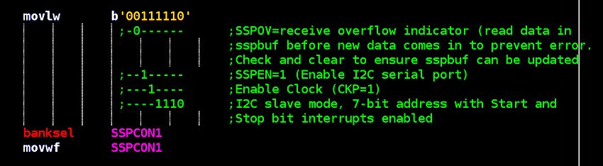
Additionally, we mask the 7 upper bits of a transmission for address detection via the SSPMSK register and give the BMC a bus address of "2" via the SSPADD register. This way, when the master device tries to communicate with the BMC, the BMC will mask out the upper seven bits of the 8-bit packet, determine if the transmission is meant for itself (if it is addressed to address #2) and trigger an interrupt if it is.
This isn't meant to be a bottom-up tutorial on the I2C protocol, so if you are new to it then I would recommend reading through Microchip's documentation in the device data sheet
Battery Monitor I2C commands
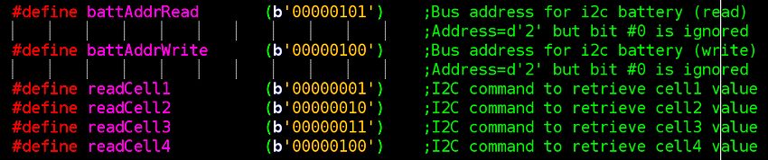
The BMC accepts four commands pertaining to the reading of cell voltages (in addition to address read or write) which are defined near the top of the program file:
When a "START" condition is transmitted by the master device (followed by the address of the slave), the microcontroller hardware automatically determines if the upper 7 bits of the transmitted address are a match. If a match is found, the hardware "ACKS" the master and then generates an interrupt.
Interrupt Handling Routine (ISR)
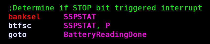
Inside the interrupt, we do the usual saving away of context variables (ie: work, STATUS and program counter registers). Also remember that an interrupt is triggered upon receiving an I2C "START" and "STOP" condition. Since we don't care about triggering interrupts on "STOP" conditions, we immediately check if such a scenario caused one (and exit the routine if it did.)
When the master device addresses the BMC slave, bits 1 through 7 hold the address and bit #0 is reserved for addressing the slave in a "write" or "read" context. If the address is determined to be a match, then bit #2 of the SSPSTAT register (of the slave device) will "mirror" bit #0 of the transmitted address. In our program, we signify a "0" as a "write", meaning that the slave is receiving a command. Whereas a "1" signifies a "read" (master is requesting data from the BMC slave device). So, depending on the STATUS of bit 2 of the SSPSTAT register we jump to the "SlaveRead" or "SlaveWrite" section of the ISR.
BMC slave receives a command from master
Let's assume the BMC has been addressed in command mode. This means that the address was a match and bit #0 of the transmission from the master was "0". (Which also means that SSPSTAT bit #2 of the BMC slave is a "0".) After the BMC slave has been put in "command mode", its hardware automatically acknowledges (ACKS) the master. The command is then sent from the master device and the BMC slave reads and checks it against a list of four possible commands that it can receive in this scenario. Each of the four commands corresponds to the loading of one of the four cell voltage values of the LiPo battery pack. Once it determines which cell the master device is commanding it to read, it proceeds to the section of code where it will load the requested value (as shown below):
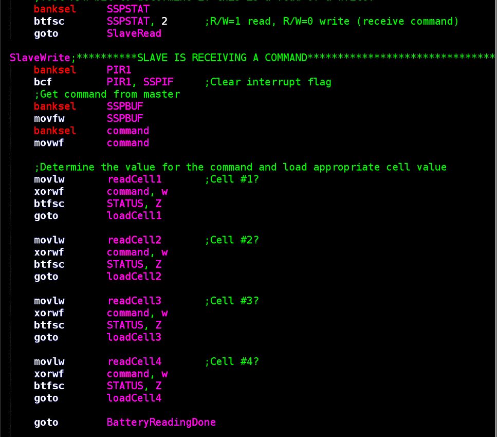
For example, if the command was found to be "readCell3" the program would then jump to the following code section:
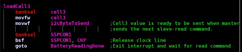
Inside the section "loadCell3", the BMC slave grabs the value for cell 3 that has previously been sampled (we have yet to cover this) and loads it into the variable named "i2cByteToSend". This variable will be clocked out on the next transmission when the master device requests the data. Finally, the I2C clock line is released (which frees it up for the master to continue communication). The BMC slave then exits the ISR and the master sends a "STOP" signal.
Master receives cell data from BMC slave
After the BMC slave has finished acting upon the reception of a command to read a battery cell (as explained above) and has released the I2C clock line, the master device then "STARTS" another transmission sequence and addresses the BMC slave in "read mode". Here the slave receives an addresses that matches it's own with bit #0 of the transmission being a "1" (which means that SSPSTAT bit #2 is a "1" also.) Once entering the ISR the program will end up at the code section labeled "SlaveRead" (shown below:)
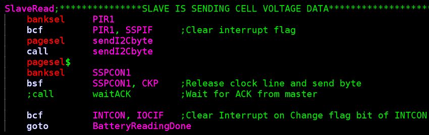
Here the BMC slave clocks out the value held in the variable named "i2cByteToSend" (which was preloaded during the last communication sequence) and then exits the ISR. The master device then puts its I2C module into "receive mode", receives the data transmitted by the BMC slave and does with it whatever its particular program tells it to.
This effectively ends the communication sequence that happens when a master device requests the voltage info for a particular battery cell. The above sequence of events happens once for every cell transmission via I2C. The master device software written for this project implements a counter that keeps track of what cell it is reading and sends the appropriate command each time. (This will be explained later). We have also yet to discuss how the BMC samples the cell voltages and encodes these values into an 8-byte I2C packet.
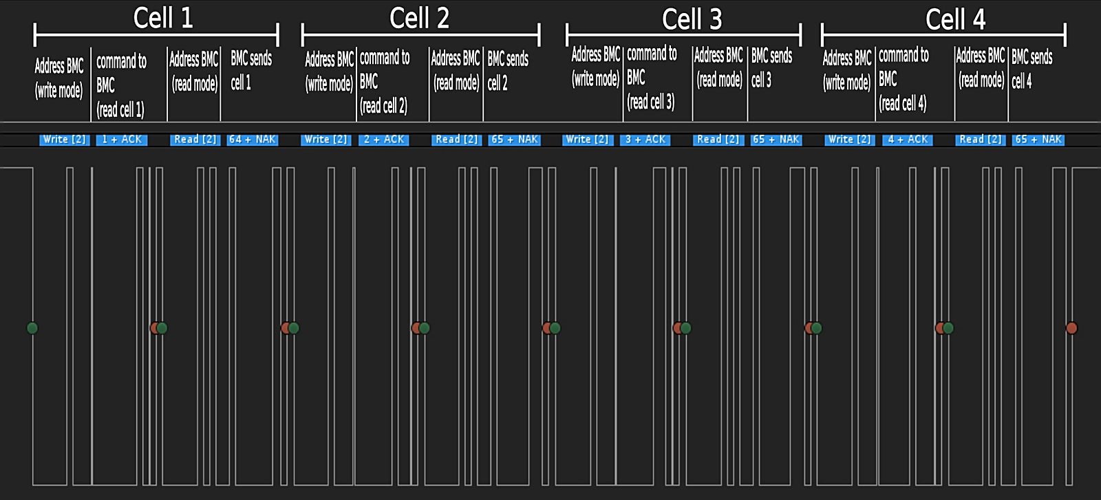
I2C communication (Logic Analyzer capture)
The following image is a screen shot of the I2C communication sequence between the master and BMC slave as the master device reads the four battery cell values from the BMC. I have added annotations to each step of the sequence to help visualize what is going on during each transmission. The green dots indicate an I2C "START" condition and the red dots indicate an I2C "STOP" condition. The logic analyzer used is from Saleae
Final thoughts on I2C communication
As I mentioned at the beginning of this page, my intention was not to teach the I2C protocol or Microchip's implentation of it in 8-bit PIC microcontrollers, but rather to explain (as best as possible) the way it is used with the battery monitoring circuit in this project. I will be honest in saying that getting two PIC MCU's to communicate with each other via I2C is not exactly a fun process. In fact it's brutally agravating at times (despite the data-sheet documentation). I found that the best method (for me) was to not try and do too much in between any "START" and "STOP" condition, but rather use a "START" and "STOP" in between every single step of the communication sequence. As you might imagine, an oscilloscope or logic analyzer with i2c protocol decoding is essential for dealing with the inevitable problems that crop up with serial communications like this.
Now that we understand how the BMC "talks" to external devices, we will now discuss how it actually determines the cell values themselves.
Continue on to battery cell sampling