Before going any further, lets take a look at the schematic of our Battery Monitoring Circuit (BMC) that accomplishes the goals stated in the previous page.
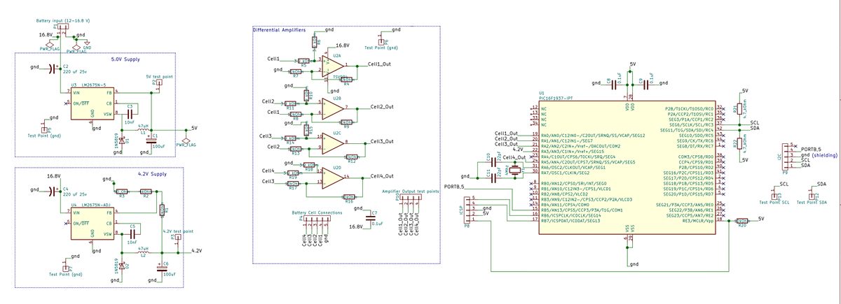
(A high-res version of the above schematic can be found here )
Voltage Regulators:
The circuit consists of two Texas Instruments switching regulators that take the unregulated battery pack voltage as inputs. One is used to supply 5V to the PIC micro and the other is used to supply a 4.2V reference voltage to the ADC module of the microcontroller. The regulator data sheet provides information on external component selection (capacitors, inductors etc...) in regards to specific inputs and outputs. For the adjustable output regulator, I used 50 ohm, 4kohm and 10kohm resistors with tolerances of 0.1% to give me an adequately precise 4.2V output.
Operational Amplifiers:
Additionally, there are four op-amps that are configured as differential amplifiers (specifically as subtractors). For more information on using op-amps with DC circuits, take a look at the DC op-amp section of this website. Specific information on differential amplifiers and subtractors can be found here. Bear in mind that the accuracy of the subtractor circuit is dependent on the matching resistor values being as close as possible. In my case I used resistors with 0.1% tolerance.
In my circuit I chose a 16 pin (two of which are empty/not-connected) quad op-amp package made by Linear Technology. This particular device is a "single supply" op-amp, meaning that a negative voltage is not required on the negative supply terminal ("V-"). Instead, the "V-" terminal is connected to ground while still allowing for output swings from 0V to +VCC ("+VCC" being the positive voltage supply coming from the battery pack). The data sheet can be found here.
The inverting and non-inverting inputs of each op-amp are connected to one of the five pins found on the JST-XH battery pack connector. Each amplifier measures the difference between the voltage on a particular pin and the voltage on the pin that precedes it (in order of the series connection of the four battery cells). Take a look at the diagram of the connector below:
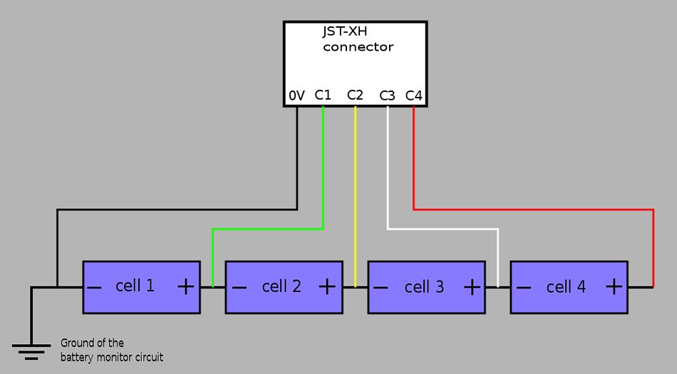
When considering the above diagram, the outputs of each op-amp are as follows
- op-amp #1 output = C1-0
- op-amp #2 output = C2-C1
- op-amp #3 output = C3-C2
- op-amp #4 output = C4-C3
Microcontroller:
The microcontroller used for our BMC is a PIC16F1937. The data-sheet for the device can be found here. We won't discuss any code just yet, but take note of the 5 connections made between analog input pins and the 4 amplifier outputs as well as the 4.2V reference voltage. Other pin connections include the I2C data and clock lines, in circuit serial programming interface (ICSP) as well as various test points for troubleshooting.
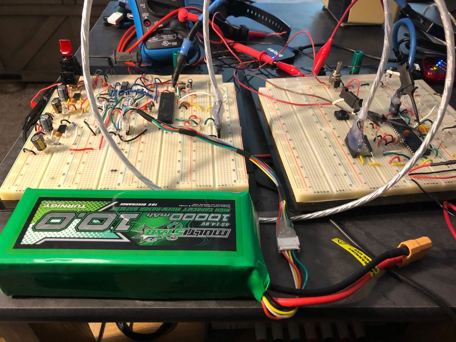
Prototyping and Testing Photos
I started with a breadboard circuit. In the photo below, the breadboard on the left is the battery monitoring circuit. The breadboard on the right simulates an external device requesting battery data and initiates communication via a push-button switch. The silver shielded cable was used for I2C communication between the boards and simulated the approximate length and type of cable I planned on using in my intended application of a submersible ROV. I2C communication was observed and debugged with a logic analyzer.
Once I felt I had a working concept, I went and designed a PCB using KICAD. I then had the PCB fabricated by Oshpark.
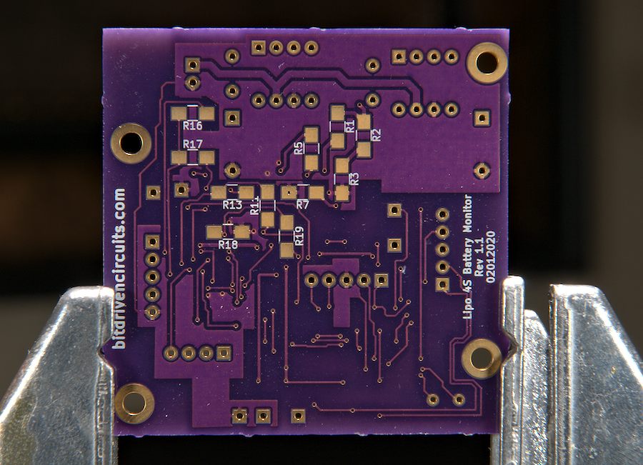
Top and Bottom sides of PCB (unpopulated)
Top:
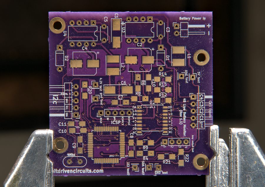
Bottom:
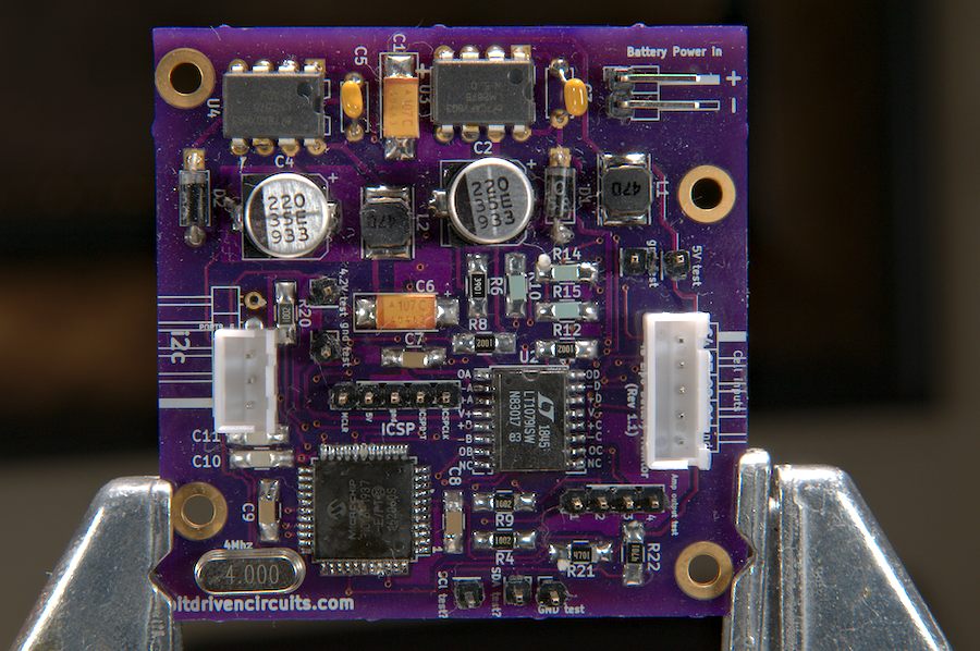
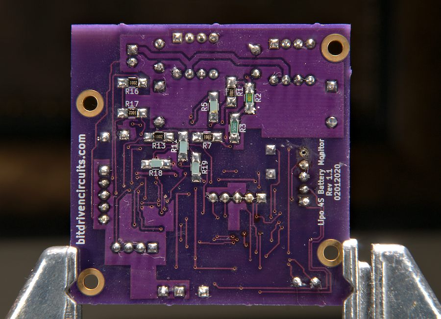
Top and Bottom sides of PCB (populated)
Top:
Bottom:
Up next we will look at the implementation of the I2C protocol that allows the BMC to communicate with an external device.
Continue on to I2C master/slave communication...