All documentation on this page references the program file for the Battery Monitoring Circuit (BMC) named batMonMain.asm.
Sampling
Cell voltage readings are performed during device startup and once during the 4 cell I2C transmission sequence between master and slave. This is done by calling the subroutine named "SamplCells". Inside "SampleCells", the ADC module is configured to use the appropriate analog input pin (depending on what cell we are reading). The AD conversion is then performed and two other subroutines named "ProcessCells" and "cellLookup" are called in order to scale and encode the cell voltages values into an 8-bit number that can be sent to the master device. For example, we see the sampling of cell #1 below:
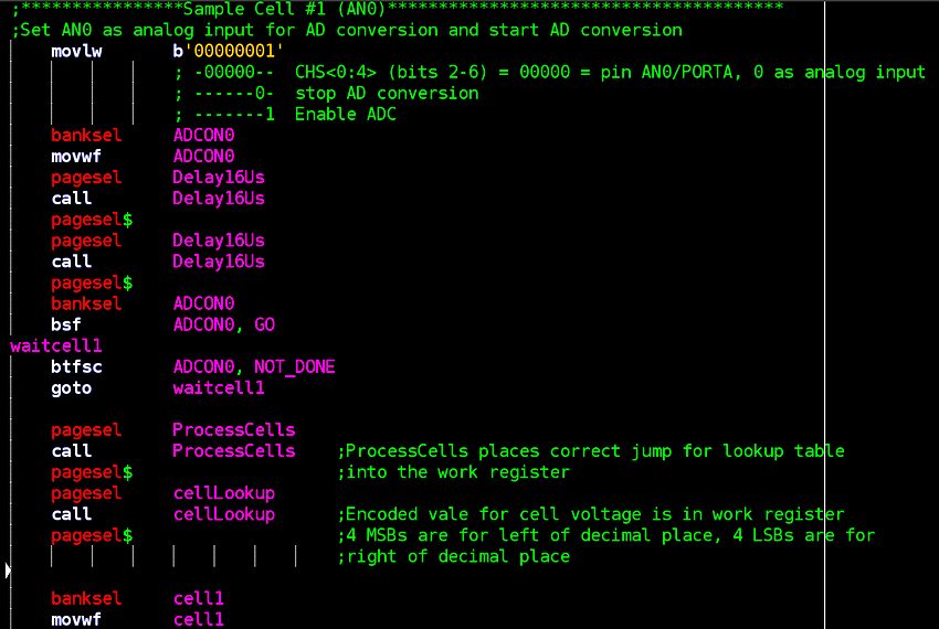
Cells 2, 3 and 4 follow immediately afterwards with the only difference being the changing of the analog input pin for the ADC module and the variable that holds the encoded result.
Scaling the ADC Results
As was mentioned above, inside the subroutine "SampleCells", two other routines are called for purposes of extracting meaningful information from the ADC and encoding the results inside an 8-bit number. The names of these routines are "ProcessCells" and "cellLookup". "ProcessCells" takes the ADC result from the battery cell and scales it to a result that represents a value between 3.0 to 4.2V with accuracy of about 0.1V. Take a look at a screen shot of the subroutine (split window to fit it into one image):
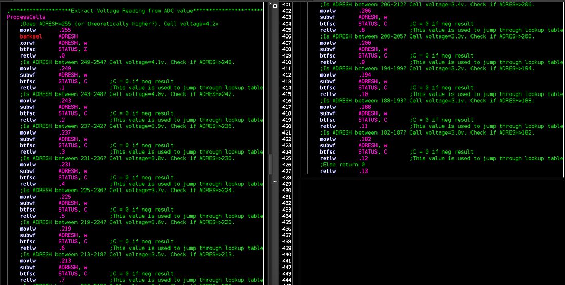
For our LiPo battery, the minimum and maximum cell voltages we want to read are 3.0 and 4.2 V respectively. The ADC being performed is 8-bit with a range of values from 0-255. Since the ADC module is configured to use the positive 4.2V external reference provided by the Battery Monitoring Circuit's (BMC) switching regulator, an ADC value of 255 represents the maximum value any single battery cell can have (4.2V). An ADC value of 182 would represent the minimum desired cell voltage value of 3.0V. For example, lets say the ADC result was 203:
- 203/255 = 0.7961
- 0.7961 * 4.2 = 3.34V
Encoding the ADC Results
Continuing with the above example of a cell voltage of 3.3V, how do we represent such a value in a single 8-bit number? This is where the lookup table found in the subroutine "cellLookup" comes into play. Once the routine "ProcessCells" determines a scaled value for the cell voltage, it exits the routine and the program returns back to "SampleCells" with a number ranging from 0-13 loaded in the work register. The range 0-13 represnts the 13 different voltage values we can have if we use 0.1V increments from 3.0-4.2V. "cellLookup" is then called and this number from 0-13 is added to the program counter causing the program to jump 0-13 program addresses forward into the lookup table. It then loads another 8-bit number into the work register that represents an encoded value of our cell voltage. The encoding scheme is as follows:
- 4 most significant bits = cell voltage value to the left of the decimal point (a "3" or "4")
- 4 least significant bits = cell voltage value to the right of the decimal point (0-9)
Let's examine the actual routine itself:
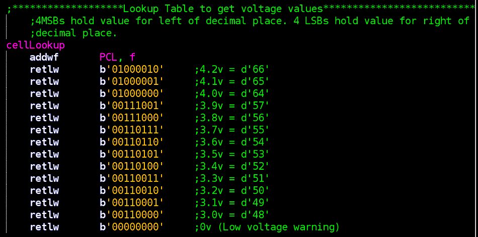
So with a cell voltage of 3.3V, "SampleCells" would would arrive at an ADC value of 203 (for arguments sake). It then calls "ProcessCells" and gets the number "9" loaded into the work register. Next (with "9" in the work reg.) "cellLookup" is called and the "9" gets added to the program counter and we end up at the following line in the lookup table:

Notice that:
- 4 msb = 0011 = decimal number "3"
- 4 lsb = 0011 = decimal number "3"
This 8-bit encoded number is loaded into the appropriate variable for it's corresponding cell voltage value and eventually transmitted to the external master device via I2C. It is up to the master device to extract the encoded data from the 8-bit number and do something meaningful with it. Of course the ADC values and lookup table above can be expanded for more granular results and wider range, but for my purposes the above process was sufficient.
Up next we will take a look at a test program to simulate communication between an external device and the BMC:
Continue on to BMC test program...