When considering an AC circuit driven by a periodic source, we consider the "effective current" to be the amount of DC current that delivers the same amount of power to a resistor as the average power delivered by a periodic current to a resistor of the same value. Consider the following AC and DC circuits:
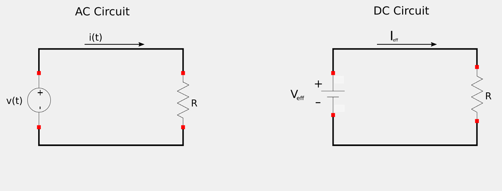
Our goal here is to find an expression for effective current (Ieff) that will transfer the same power to the resistor in the DC circuit as does the periodic current i(t) in the AC circuit. For the AC circuit, the average power absorbed by the resistor can be defined as: $$ \bar{p} = \frac{1}{T} \int_0^T i^2R \; dt $$ $$ \bar{P} = \frac{R}{T} \int_0^T i^2 \; dt \qquad,(A) $$ For the DC circuit, the power absorbed by the resistor is defined as: $$ p = I^2_{eff}R \qquad,(B) $$ Equating expressions A and B gives us: $$ I^2_{eff}R = \frac{R}{T} \int_0^T i^2 \; dt $$ $$ I_{eff} = \sqrt{\frac{1}{T} \int_0^T i^2 \; dt} \qquad, (C) $$ Expression C tells us that the effective value is the square root of the mean (average) of the square of the periodic signal. For this reason, the "effective value" is commonly referred to as the "root mean square" or "RMS" value. $$ I_{eff} = I_{rms} , \qquad V_{eff} = V_{rms} $$
General expression for RMS values:
For any periodic function x(t), the RMS value is defined as: $$ X_{rms} = \sqrt{\frac{1}{T} \int_0^T x^2 \; dt} $$
Deriving an expression for the RMS value of a sinusoidal signal:
A periodic signal can be a square wave, triangle wave etc.., but what if it is the commonly encountered sinusoid? Let's begin by considering a sinusoidal current defined as: $$ i(t) = I_m\cos(\omega t + \theta_i) $$ We now know that we can defined the RMS current as: $$ I_{rms} = \sqrt{\frac{1}{T} \int_0^T i^2 \; dt} $$ Plugging in our expression for the current gives us: $$ I_{rms} = \sqrt{\frac{1}{T} \int_0^T I^2_m\cos^2(\omega t + \theta_i) \; dt} \qquad,(Eqn \; 1)$$
Recall the following trig identity for the square of a cosine function: $$ \cos^2(\theta) = \frac{1}{2} \cos(2\theta) + 1 $$ Also note that: $$ \omega = 2\pi f, \; f = \frac{\omega}{2\pi} $$ and that: $$ period = T = \frac{1}{f} = \frac{2\pi}{\omega} $$ Applying all of this to equation #1 gives us the following:
$$ I_{rms} = \sqrt{\frac{I^2_m \omega}{2\pi} \int_0^{\frac{2\pi}{\omega}} \frac{1}{2} \cos(2\omega t + 2\theta_i) + 1\; dt} $$ $$ = \sqrt{\frac{I^2_m \omega}{4\pi} \int_0^{\frac{2\pi}{\omega}} \cos(2\omega t + 2\theta_i) + 1\; dt} $$ I'm not going to evaluate the integral (using u-substitution) step by step here, but you should get the following when you do: $$ I_{rms} = \sqrt{\frac{I_m^2}{8\pi} [\sin(2\omega t + 2\theta_i) + 2\omega t + 2\theta_i]} \Big|_0^{\frac{2\pi}{\omega}}$$
$$ = \sqrt{\frac{I_m^2}{8\pi} \Big[ \sin\Big(\frac{4\pi\omega}{\omega} + 2\theta_i\Big) + \frac{4\pi \omega}{\omega} + 2\theta_i \Big] - \frac{I_m^2}{8\pi} [\sin(2\theta_i) + 2\theta_i] }$$
Take note of the fact that: $$ \sin\Big(\frac{4\pi\omega}{\omega} + 2\theta_i\Big) = sin(2\theta_i) $$ ...and continue evaluating the above expression:
$$ I_{rms} = \frac{I_m}{\sqrt{2}} \qquad,(Eqn\;2)$$
Using a similar procedure for a sinusoidal voltage we would get:
$$ V_{rms} = \frac{V_m}{\sqrt{2}} \qquad,(Eqn\;3) $$
Note that equations 2 and 3 are only valid for sinusoidal signals, and can't be applied to other periodic sources such as square-waves, triangle waves etc...
Average power in terms of RMS values:
Recall that average power is defined as: $$ \bar{p} = \frac{1}{2} V_m I_m \cos(\theta_v-\theta_i) $$ Rearranging equations 2 and 3 (just above) allows us to substitute for Vm and Im: $$ \bar{p} = \frac{1}{2}(V_{rms} \sqrt{2})(I_{rms} \sqrt{2}) \cos(\theta_v-\theta_i) $$
$$ \bar{p} = V_{rms} I_{rms} \cos(\theta_v-\theta_i) \qquad(Eqn\;4)$$
For the average power absorbed by a resistor (In terms of RMS):
Recall that for a purely resistive load: $$ \bar{p} = \frac{1}{2} V_m I_m \qquad, and \; V_m = I_m R $$ $$ = \frac{1}{2} I_m^2 R $$ Rearranging equation two (found above) we can substitute for the Im squared term: $$ \bar{p} = \frac{1}{2} (2) I_{rms}^2 R $$
$$ \bar{p} = I_{rms}^2 R \qquad,(Eqn\;5) \; For \; a \; purely \; resistive \; load $$
Also, note that: $$ I_{rms} = \frac{V_{rms}}{R} $$ If we substitute that into equation #5, we get: $$ \bar{p} = \frac{V_{rms}^2}{R^2}R $$ ...which reduces to the following and gives us another RMS expression for power absorbed by a resistor:
$$ \bar{p} = \frac{V_{rms}^2}{R} \qquad,(Eqn\;6) \; For \; a \; purely \; resistive \; load $$
Let's look at an RMS example problem:
Continue on to RMS example problem...