Complex power is used to analyze the effects of parallel loads on a circuit. Once you are able to express the complex power of a given load, you effectively have an expression that contains all of the information regarding the power absorbed by that load. Consider the following AC circuit:
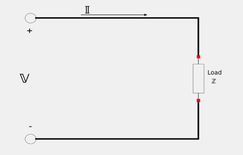
Where: $$ \mathbb{V} = V_m \angle \theta_v $$ $$ \mathbb{I} = I_m \angle \theta_i $$ If you recall equation #6 from our study of instantaneous and average power, we defined average power as: $$ P = \frac{1}{2} R_e \{ \mathbb{V} \mathbb{I} * \} = \frac{1}{2} V_m I_m \cos(\theta_v - \theta_i) \qquad, Eqn \; 6 $$ However, equation #6 is only the real part of a larger complex expression that was:
$$ \frac{1}{2} \mathbb{V} \mathbb{I} * = \Big[ \frac{1}{2} V_m I_m \cos(\theta_v - \theta_i) \Big] + j \Big[ \frac{1}{2} V_m I_m \sin(\theta_v - \theta_i) \Big] \qquad , Eqn \; 7 $$
Expression #7 contains all of the information regarding the power absorbed by a given load and has both real and imaginary parts. For this reason we label Exression #7 as "Complex Power." We will designate complex power as:
$$ \mathbb{S} = \frac{1}{2} \mathbb{V} \mathbb{I} * = \Big[ \frac{1}{2} V_m I_m \cos(\theta_v - \theta_i) \Big] + j \Big[ \frac{1}{2} V_m I_m \sin(\theta_v - \theta_i) \Big] \;\;, Eqn \; 8$$
Recall the definition of RMS voltage values: $$ \mathbb{V}_{rms} = \frac{\mathbb{V}}{\sqrt{2}} $$ $$ \mathbb{I}_{rms} = \frac{\mathbb{I}}{\sqrt{2}} $$ ...which allow us to put equation #8 in terms of RMS values:
$$ \mathbb{S} = \mathbb{V}_{rms} \mathbb{I}_{rms}* = [ V_{rms} \; I_{rms} \cos(\theta_v - \theta_i) ] + j [ V_{rms} \; I_{rms} \sin(\theta_v - \theta_i) ] \;\;,(Eqn\;9) $$
...where the asterisk (*) represents the complex conjugate of the RMS phasor current.
Expanding equation #9: $$ \mathbb{S} = [V_{rms} \angle \theta_v][I_{rms} \angle (-\theta_i)] $$
$$ \mathbb{S} = V_{rms} \; I_{rms} \angle (\theta_v-\theta_i) \qquad,(Eqn\;10)$$
Recall our discussion of apparent power/power factor , and notice that in equation #10: $$ V_{rms} \; I_{rms} = apparent \; power \; (S) $$ ...and that: $$ (\theta_v-\theta_i) = power \; factor \; angle $$
Additional Expressions for Complex Power:
Complex power can also be expressed in terms of the load impedance where: $$ \mathbb{Z} = \frac{\mathbb{V}}{\mathbb{I}} = \frac{\mathbb{V}_{rms}}{\mathbb{I}_{rms}} $$ ...and therefore we also have: $$ \mathbb{V}_{rms} = \mathbb{Z}\mathbb{I}_{rms} \qquad,(A)$$ ...and: $$ \mathbb{I}_{rms} = \frac{\mathbb{V}_{rms}}{\mathbb{Z}} \qquad, (B)$$ Substituting expression A into equation #9 gives us: $$ \mathbb{S} = \mathbb{Z} \; \mathbb{I}_{rms} \; \mathbb{I}_{rms}* $$ $$ = \mathbb{Z}[I_m\angle \theta_i] \; [I_m \angle (-\theta_i)] $$
$$ \mathbb{S} = I^2_{rms} \mathbb{Z} \qquad, (Eqn\;11) $$
Additionally, if we substitute expression B into equation #9 , we get: $$ \mathbb{S} = \mathbb{V}_{rms} \Big( \frac{\mathbb{V}_{rms}*}{\mathbb{Z}*} \Big) $$ $$ = \frac{[V_{rms}\angle \theta_v] [V_{rms}\angle (-\theta_v)]}{\mathbb{Z}*} $$
$$ \mathbb{S} = \frac{V^2_{rms}}{\mathbb{Z}*} \qquad, (Eqn\;12)$$
We now have four expressions for complex power:
$$ 1) \; \mathbb{S} = I^2_{rms} \mathbb{Z} $$ $$ 2) \; \mathbb{S} = \frac{V^2_{rms}}{\mathbb{Z}*} $$ $$ 3) \; \mathbb{S} = \mathbb{V}_{rms} \mathbb{I}_{rms}* $$ $$ 4) \; \mathbb{S} = V_{rms} \; I_{rms} \angle (\theta_v-\theta_i) $$ Additionally, the magnitude of the complex power equals the apparent power: $$ |\mathbb{S}| = S $$
Real Power and Reactive Power:
Recall that: $$ \mathbb{Z} = R+jX $$ Also, note our 1st expression for complex power: $$ \mathbb{S} = I^2_{rms} \mathbb{Z} $$ Expanding the 1st expression for complex power to include our above definition of impedance gives us: $$ \mathbb{S} = I^2_{rms} (R+jX) $$ $$ \mathbb{S} = P+jQ $$ ...where P and Q are the real and imaginary parts of the complex power. $$ P = average \;(or \; real) \; power $$ $$ \qquad = R_e \{ \mathbb{S} \} $$ $$ \qquad = I_{rms}^2 \; R $$ $$ Q = reactive \; power $$ $$ \qquad = I_m \{ \mathbb{S} \} $$ $$ \qquad = I_{rms}^2 \; X $$
Additionally, consider equation #9 (complex power in terms of RMS values): $$ \mathbb{S} = [ V_{rms} \; I_{rms} \cos(\theta_v - \theta_i) ] + j [ V_{rms} \; I_{rms} \sin(\theta_v - \theta_i) ] $$ We recognize that this expression for complex power has both a real and imaginary part. We will let: $$ Real \; part = P = V_{rms} \; I_{rms} \cos(\theta_v - \theta_i) $$ $$ Imaginary \; part = Q = V_{rms} \; I_{rms} \sin(\theta_v - \theta_i) $$
Real Power (P):
Real power is the average power (measured in watts) delivered to the load. It can be considered "useful" power, or the actual power dissipated by the load.
Reactive Power (Q):
Reactive Power is considered the energy exchange that takes place between the source and the reactive parts of the load. It is measured in "volt-ampere reactive" (VAR). Energy storage elements such as capacitors and inductors neither dissipate nor supply power. Rather, they exchange it back and forth with the rest of the circuit. Therefore, reactive power is transferred back and forth between the load and the source.
Summary of expressions for Real and Reactive Power:
Real Power = P $$ P = R_e \{ \mathbb{S} \} $$ $$ \qquad = V_{rms} \; I_{rms} \cos(\theta_v - \theta_i) $$ $$ \qquad = S \cos(\theta_v - \theta_i) $$ $$ \qquad = I_{rms}^2 \; R $$ $$ Real \; power \; depends \; on \; the \; load's \; resistance \; (R) $$ Reactive Power = Q $$ Q = I_m \{ \mathbb{S} \} $$ $$ \qquad = V_{rms} \; I_{rms} \sin(\theta_v - \theta_i) $$ $$ \qquad = S \sin(\theta_v - \theta_i) $$ $$ \qquad = I_{rms}^2 \; X $$ $$ Rective \; power \; depends \; on \; the \; load's \; reactance \; (X) $$
We now take note of the following three conditions with regards to reactive power (Q):
For a resistive load:
$$ Q = 0 $$ $$ P_f = 1 $$
For a capacitive load:
$$ Q \lt 0 $$ $$ Leading \; P_f $$
For an inductive load:
$$ Q \gt 0 $$ $$ Lagging \; P_f $$
Power Triangle:
The "power triangle" is a visual reference that helps in understanding the relationship between P, Q, complex power and the power factor angle. By using the power triangle, if you are given any two of these components, you can find the other two.
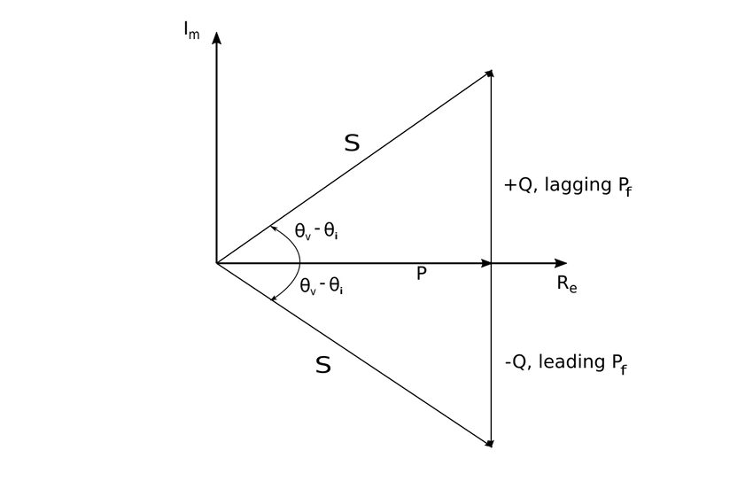
Complex power can also lie within the 2nd and 3rd quadrants if the load impedance has a negative resistance (possible with active circuits).
Conservation of AC Power:
The Law of Conservation of Power applies to AC circuits just as it does with DC. For a circuit with a source and multiple loads, the total power supplied by the source equals the sum of all the powers delivered to each individual load. Therefore, for a source connected to "n" number of loads: $$ \mathbb{S} = \mathbb{S}_1 + \mathbb{S}_2 + \mathbb{S}_n $$ The above expression is in terms of complex power, but the same expression would hold true for instantaneous, real and reactive power. (It would not hold true for apparent power however.)
We will now go ahead and look at some example problems involving the use of complex power.
Continue on to Complex Power example problem #1...