Determine A) the phasor current (I) and B) the power factor of the following circuit with given information:
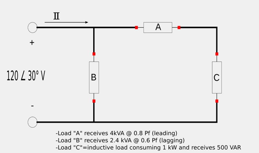
(note: the voltage source is given in terms of RMS value.)
A) Determine the current flowing out of the voltage source:
Our strategy involves using the third expression for complex power (found in the intro to complex power page.) $$ \mathbb{S} = \mathbb{V}_{rms} \; \mathbb{I}_{rms}* $$ ...where the complex power of the circuit is equal to the sum of the complex powers for each individual load: $$ \mathbb{S} = \mathbb{S}_A + \mathbb{S}_B + \mathbb{S}_C $$
Determine the complex power for load "A":
Recall the following expression for complex power in terms of real and reactive power: $$ \mathbb{S} = P+jQ \qquad, Expression \; 1$$ For load "A" we have already been given the following: $$ S_A = 4,000 $$ $$ P_{fA} = 0.8 $$ Recall that equation #2 from the tutorial on apparent power and the power factor allows us to expression real power in terms of apparent power and the power factor such that: $$ P_A = S_A P_{f_A} $$ $$ = 4000(0.8) $$ $$ P_A = 3200 \; W $$
Additionally, we know that power factor for load "A" can be expressed as: $$ P_{fA} = \cos(\theta_{V_A} - \theta_{i_A}) = 0.8 $$ therefore: $$ \theta_{V_A} - \theta_{i_A} = cos^{-1}(0.8) $$ $$ \theta_{V_A} - \theta_{i_A} = 36.87^{\circ} $$ We now turn to the power triangle to calculate the reactive power for load "A":
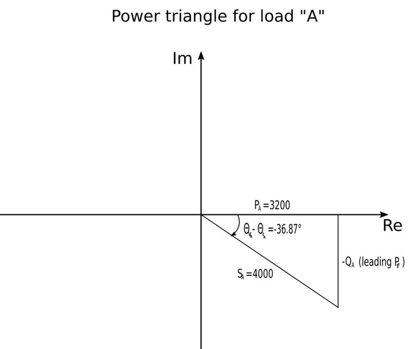
We know that the power triangle is in the 4th quadrant and that the power factor angle is negative because we were told that the power factor was "leading." Through simple trigonometry we can determine that: $$ \tan(-36.87^{\circ}) = \frac{Q_A}{3200} $$ $$ Q_A -2400 \; VAR $$ Recalling Expression #1 we can now solve for the complex power of load "A": $$ \mathbb{S}_A = P_A + jQ_A $$
$$ \mathbb{S}_A = (3200-j2400) \; VA $$
Determine the complex power for load "B":
To determine the complex power for load "B" we proceed as we did with load "A". For load "B" we have already been given the following: $$ S_B = 2,400 $$ $$ P_{fA} = 0.6 $$ Calculate the real power for load "B": $$ P_B = S_B \; P_{f_B} = 2400(0.6)$$ $$ P_B = 1440 \; W $$ Now calculate the power factor angle: $$ P_{f_B} = 0.6 = \cos(\theta_{V_B} - \theta_{i_B}) $$ $$ \theta_{V_B} - \theta_{i_B} = \cos^{-1}(0.6) $$ $$ \theta_{V_B} - \theta_{i_B} = 53.13^{\circ} $$ Now construct a power triangle for load "B":
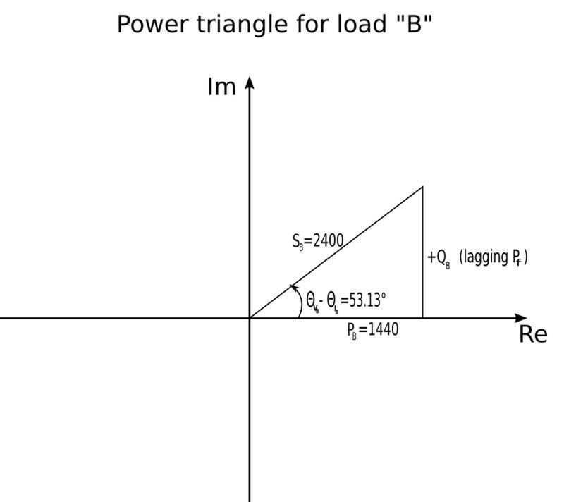
The power triangle is now used to determine the reactive power (Q) for load "B": $$ \tan(53.13^{\circ}) = \frac{Q_B}{1440}$$ $$ Q_B = 1920 \; VAR $$ Recalling Expression #1 we can now solve for the complex power of load "B": $$ \mathbb{S}_B = P_B + jQ_B $$
$$ \mathbb{S}_B = (1440+j1920) \; VA $$
Determine the complex power for load "C":
For load "C" we were given: $$ P_C = 1,000 \; W $$ $$ Q_C = 500 \; VAR $$ ...which allows us to quickly and easily express the complex power of load "C" as:
$$ \mathbb{S}_C = (1000+j500) \; VA $$
The reactive power of the circuit is defined as: $$ \mathbb{S} = \mathbb{S}_A + \mathbb{S}_B + \mathbb{S}_C $$ $$ = (3200-j2400) + (1440+j1920) + (1000+j500) $$ $$ = (5640 + j20) \; VA $$
$$ \mathbb{S} = 5640 \angle 0.2032^{\circ} $$
Using the third expression for complex power (found in the intro to complex power) page: $$ \mathbb{S} = \mathbb{V}_{rms} \; \mathbb{I}_{rms}* $$ $$ \mathbb{I}_{rms}* = \frac{5640 \angle 0.2032^{\circ}}{120 \angle 30^{\circ}} $$ $$ \mathbb{I}_{rms}* = 47 \angle (-29.8^{\circ}) $$ Remember that the above expression is the complex conjugate of the current and that we need to account for the sign of the angle to get the actual value of the current
Answer to part A:
$$ \mathbb{I}_{rms} = 47 \angle (29.8^{\circ}) $$
B) Determine the power factor of the circuit:
Once again we turn to the definition of complex power used throughout this page: $$ \mathbb{S} = \mathbb{V}_{rms} \; \mathbb{I}_{rms}* $$ ...which can also be expressed as: $$ \mathbb{S} = V_{rms} \angle \theta_V \; I_{rms} \angle (-\theta_i) $$ $$ \mathbb{S} = V_{rms}I_{rms} \angle (\theta_V - \theta_i) $$ ...where: $$ (\theta_V - \theta_i) = power \; factor \; angle $$ Above, when we calculated the complex power of the circuit we determined that the numerical value for the power factor angle was: $$ (\theta_V - \theta_i) = 0.2032^{\circ} $$ We can now calculate the power factor using our previously discussed definition: $$P_f = \cos (\theta_V - \theta_i)$$ $$ = \cos(0.2032^{\circ}) $$ ...which gives us the answer to part B of the original question:
$$P_f = 0.9999 \approx 1 $$