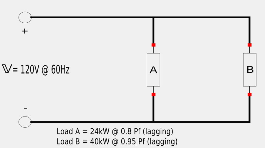
Given the following circuit:
A) Determine the power factor of the parallel load combination.
B) Calculate the value of the parallel capacitor required to correct the power factor to unity.
A) Start by determining an expression for the complex power of the parallel load combination:
Obtain an expression for the complex power of load "A":
Real Power for load "A": $$ P_A = 24 \; kW $$ Apparent power for load "A": $$ S_A = \frac{P_A}{P_{f_A}} = \frac{24 \; kW}{0.8} = 30 \; kVA $$ Power factor angle for load "A": $$ \cos(\theta_A) = 0.8 $$ $$ \theta_A = \cos^{-1}(0.8) = 36.87^{\circ} $$ Reactive power for load "A": $$ Q_A = S_A \sin(\theta_A) $$ $$ = 30,000 \sin(36.87^{\circ}) $$ $$ Q_A = 18 \; kVAR $$ The complex power for load "A": can now be expressed as: $$\mathbb{S}_A = P_A + jQ_A $$ $$ \mathbb{S}_A = 24,000 + j 18,000 \qquad (Eqn \; 1) $$
Obtain an expression for the complex power of load "B":
Real Power for load "B": $$ P_B = 40 \; kW $$ Apparent power for load "B": $$ S_B = \frac{P_B}{P_{f_B}} = \frac{40 \; kW}{0.95} = 42,105 \; VA $$ Power factor angle for load "B": $$ \cos(\theta_B) = 0.95 $$ $$ \theta_B = \cos^{-1}(0.95) = 18.19^{\circ} $$ Reactive power for load "B": $$ Q_B = S_B \sin(\theta_B) $$ $$ = 42,105 \sin(18.19^{\circ}) $$ $$ Q_B = 13,144 \; VAR $$ The complex power for load "B": can now be expressed as: $$\mathbb{S}_B = P_B + jQ_B $$ $$ \mathbb{S}_B = 40,000 + j 13,144 \qquad (Eqn \; 2) $$
Apply the law of conservation of AC power to get the complex power of the circuit:
$$ \mathbb{S} = \mathbb{S}_A + \mathbb{S}_B $$ Substituting equations 1 and to into the above expression gives us: $$ \mathbb{S} = (24,000 + j 18,000) + (40,000 + j 13,144) $$ $$ \mathbb{S} = 64,000 + j31,144 = 71,175 \angle 25.95^{\circ} \qquad (Eqn \; 3) $$ The real power of the circuit will be: $$ P = 64,000 \; W $$ From equation #3 we see that : $$ 25.95^{\circ} = (\theta_v - \theta_i) = power \; factor \; angle $$ We can now determine the power factor of the original circuit: $$ P_f = \cos(25.95^{\circ}) $$
$$ P_f = 0.899 $$
B) Determine the capacitor value required to correct power factor to unity:
In order to get a power factor of "1" we need the new power factor angle to be 0 degrees (cos[0]=1). Recall the formula for the capacitance value required to achieve a unity power factor for an inductive load (found on the previous page) $$ C = \frac{P[\tan(\theta_1) - \tan(\theta_2)]}{\omega V^2_{rms}} $$ ...where: $$ \theta_2 = new \; power \; factor \; angle = 0^{\circ} $$ Recall that : $$ \omega = 2 \pi f $$ and the frequency (f) of our circuit was given to us as 60 Hz. Therefore: $$ \omega = 120 \pi $$ We now have all of the necessary information to determine the required capacitor value: $$ C = \frac{64,000[\tan(25.95^{\circ}) - \tan(0^{\circ})]}{120 \pi (120)^2} $$
$$ C = 5.74 \; \mu F $$