Balanced three-phase voltages are often produced with a 3-phase AC generator such as the one depicted below:
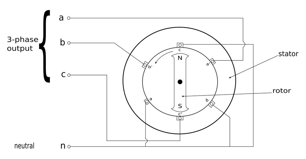
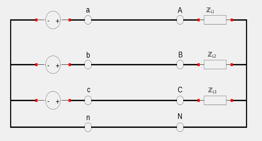
The stator contains three separate windings. In the diagram above, the presence (or lack thereof) of an apostrophe designates whether the winding is going into or out of the page as you view the generator head-on. These three windings/coils are: $$ a-a' $$ $$ b-b' $$ $$ c-c' $$ The three windings are physically spaced 120 degrees apart around the stator. Meanwhile, the rotor consists of a rotating magnet. As the magnet rotates, its magnetic field induces a voltage in each coil. Each voltage is equal in magnitude but 120 degrees out of phase with each other. Since each coil is essentially a single-phase generator, a 3-phase generator can supply power to both single and three-phase loads. Below we have a 3-phase 4-wire system connected to 3 loads:
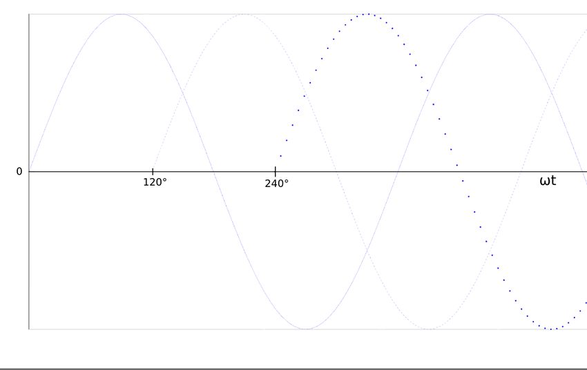
Since each winding of the alternator is acting as a voltage source and each of them are 120 degrees out of phase from each other, they will produce sinusoidal voltages that look something like the graph below:
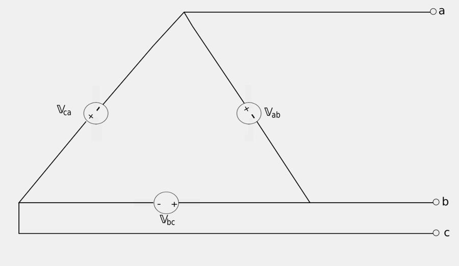
Additionally, three-phase voltage sources can either be connected in a wye or delta fashion.
Delta-connected voltage source:
Wye-connected voltage source:
For now we will focus our attention on Y-connected voltage sources.
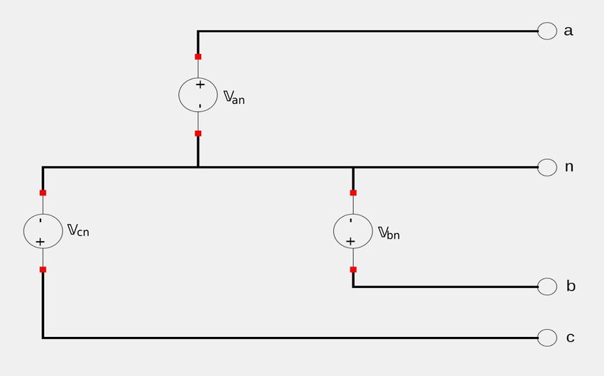
Wye-connected three-phase voltages:
First let's address some terminology. When examining the the above schematic for a Y-connected source know that: $$ \mathbb{V}_{an}, \mathbb{V}_{bn}, \mathbb{V}_{cn} = "phase \; voltages" $$ A phase-voltage is the voltage across any single component. In the case of a Y-connected voltage source, it is the voltage difference between an output line and the neutral line. Additionally, $$ \mathbb{V}_{ab}, \mathbb{V}_{bc}, \mathbb{V}_{ac} = "line \; voltages" $$ A line voltage is the voltage difference between two conductive outputs.
Balanced Voltages:
IF all three of the voltage sources have the same amplitude and frequency AND they are out of phase with each other by 120 degrees THEN the voltages are said to be "balanced." Balanced voltages implies that: $$ \mathbb{V}_{an} + \mathbb{V}_{bn} + \mathbb{V}_{cn} = 0 \qquad,(Eqn \; 1) $$ $$ |\mathbb{V}_{an}| = |\mathbb{V}_{bn}| = |\mathbb{V}_{cn}| \qquad,(Eqn \; 2) $$
Sequences:
Since the three phase voltages are 120 degrees out of phase with each other, the are two different sequential combinations that can occur.
"abc" sequence, ("positive" sequence):
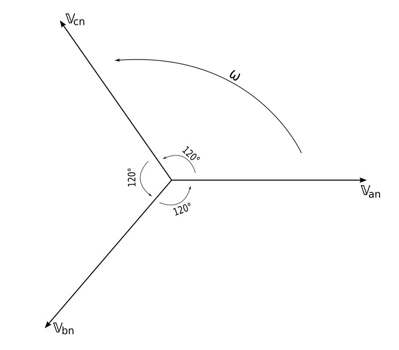
This occurs when the rotor rotates in a counter-clockwise direction. In such a scenario we have: $$ \mathbb{V}_{an} = V_p \angle 0^{\circ} $$ $$ \mathbb{V}_{bn} = V_p \angle (-120^{\circ}) $$ $$ \mathbb{V}_{cn} = V_p \angle (-240^{\circ}) = V_p \angle 120^{\circ}$$ ...where Vp represents an "effective"/RMS value. We see that V_an leads V_bn which in turn leads V_cn.
"acb" sequence, ("negative" sequence):
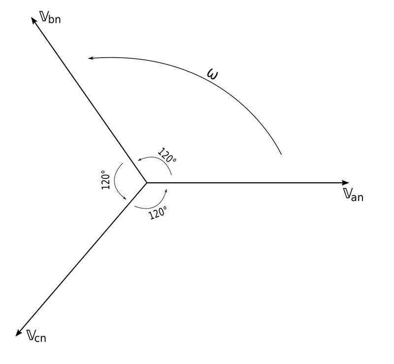
This occurs when the rotor rotates in a clockwise direction. In such a scenario we have: $$ \mathbb{V}_{an} = V_p \angle 0^{\circ} $$ $$ \mathbb{V}_{cn} = V_p \angle (-120^{\circ}) $$ $$ \mathbb{V}_{bn} = V_p \angle (-240^{\circ}) = V_p \angle 120^{\circ}$$ Here we see that V_an leads V_cn which in turn leads V_bn.
Both the "abc" and "acb" sequences satisfy equation #1 for a balanced load. For example: $$ \mathbb{V}_{an} + \mathbb{V}_{bn} + \mathbb{V}_{vn} = V_p \angle 0^{\circ} + V_p \angle (-120^{\circ}) + V_p \angle 120^{\circ} $$ $$ = \mathbb{V}_p[1\angle 0^{\circ} + 1\angle (-120^{\circ}) + 1\angle 120^{\circ}] $$ $$ = \mathbb{V}_p\Big[ (1+j0)+(-0.5-j\frac{\sqrt{3}}{2})+(-0.5+j\frac{\sqrt{3}}{2}) \Big] $$ $$ =\mathbb{V}_p[0] $$ $$ = 0 $$ They will also satisfy equation #2.
Phase sequence:
In general, the "phase sequence" is the order (in time) in which the voltages pass through their respective maximum values. It is also determined by the order in which the phasors pass through a fixed point in the phasor diagram.
Next we will explore Balanced three-phase loads...