In communications, the filtering of signals is used to select a desired signal from a multitude of other signals in the same range (or reduce the effects of noise/interference).
Resonant circuit application (radio receiver)
Series and parallel resonant circuits are used to separate an audio signal from the radio frequency carrier wave.
Block Diagram of AM radio receiver (superheterodyne):
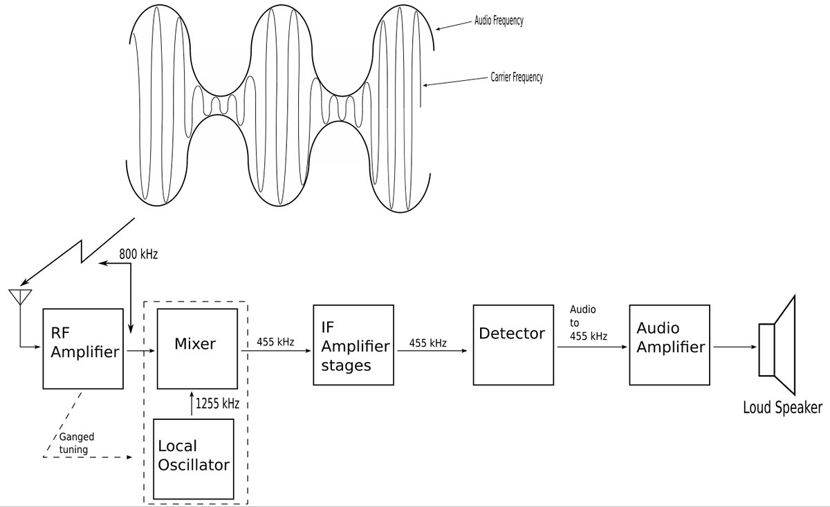
From the diagram we can see that the antenna receives amplitude modulated radio waves containing different frequencies from different broadcasting stations. A band-pass filter (which is a resonant circuit) then selects one of the incoming frequencies. The signal is still relatively weak and is thus amplified in stages to generate an audible audio frequency wave. Let's briefly describe these amplifier stages:
Radio Frequency (RF) Amplifier
-amplifies the selected broadcast signal
Intermediate Frequency (IF) Amplifier
-amplifies an internally generated signal based on the RF signal
Audio Amplifier
-amplifies the audio signal just before it reaches the speaker.
Additionally, this particular block diagram represents a particular type of receiver known as a superheterodyne receiver.
Characteristics of a Superheterodyne Receiver
Frequency Mixer
In this type of receiver, the frequency mixer (heterodyne circuit) omits the need for each amplifier stage to have multiple tuned circuits in order to cover the entire AM band (540-1600 kHz). The frequency mixer always produces the same intermediate frequency signal (445 kHz) but retains the audio frequencies carried by the incoming signal.
Ganged Tuning
The local oscillator is gang-tuned with the RF amplifier. This produces an RF signal that is combined with the incoming wave from the frequency mixer. The resulting output is a signal that contains the sum and difference frequencies of the two signals.
For example:
A resonant circuit is tuned to receive an 800 kHz incoming signal. In order to have an IF signal of 445 kHz, the local oscillator must produce a 1,255 kHz signal. $$ sum = (1,255 + 800) = 2,055 \; kHz $$ $$ difference = (1,255 - 800) = 455 \; kHz $$ While both the sum and difference are available at the output of the mixer, in practice, only the difference (455 kHz) is used. All IF amplifier stages are tuned to this frequency regardless of the broadcast stations set on the dial.
Detector stage
The detector extracts the original audio signal by removing the IF signal.
In the next page we will look at an example problem that analyzes the frequency response of a radio receiver.
Continue on to radio receiver example problem ...