One disadvantage of passive filters is that they can't achieve a gain greater than one, nor can they add energy to the circuit. Additionally, they require the use of inductors which take up space and add cost to the circuit. Below the audio range (300-3,000 Hz) they also tend to perform poorly.
Active filters can be constructed using resistors, capacitors and op-amps. They are generally less expensive and are able to provide amplifier gain while attaining the same frequency response as an RLC filter. They can also be combined with buffers/voltage followers in order to provide isolation between filter stages and the load/source impedances. The individual stages can be independently designed and chained together in order to obtain the desired transfer function. When the individual transfer functions are chained together, the Bode Plots can be added together since they are logarithmic. On the other hand, active filters are generally less reliable and stable with frequencies above 100 kHz.
4 types of Active Filters
We will focus on the following four active filter types:
- 1st order low-pass
- 1st order high-pass
- Band-pass
- Band-reject
General 1st order active filter
A general representation of an active filter is shown below:
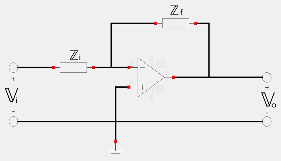
The impedance values for the input and feedback impedances determine whether the filter is high or low pass.
Transfer function fo general 1st order active filters
Recall that transfer function for voltage gain is: $$ \mathbb{H}(\omega) = \frac{\mathbb{V}_o(\omega)}{\mathbb{V}_i(\omega)} $$ Also, notice how the general 1st order active filter is an inverting amplifier. For an inverting amplifier, the DC gain is: $$ gain = \frac{-R_f}{R_i} $$ or, for AC: $$ gain = \frac{-\mathbb{Z}_f}{\mathbb{Z}_i} $$
Therefore, the transfer function for a general 1st order active filter is: $$ \mathbb{H}(\omega) = \frac{-\mathbb{Z}_f}{\mathbb{Z}_i} \qquad,(Eqn\;1) $$
1st Order Low-Pass Filter
The 1st order low-pass filter is represented in the schematic below:
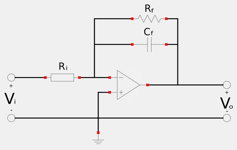
When comparing the above schematic to the schematic for a general 1st order active filter we see that: $$ \mathbb{Z}_i = R_i $$ ...and: $$ \mathbb{Z}_f = R_f||\mathbb{Z}_{C_f} $$ So, for the feedback impedance we have: $$ \mathbb{Z}_f = \frac{R_f(\mathbb{Z}_{C_f})}{R_f+\mathbb{Z}_{C_f}} $$ $$ \quad = \frac{\frac{R_f}{j\omega C_f}}{R_f+\frac{1}{j\omega C_f}} $$ $$ \mathbb{Z}_f = \frac{R_f}{1+j\omega C_fR_f} $$ Now recall equation #1 for a general 1st order active filter: $$ \mathbb{H}(\omega) = \frac{-\mathbb{Z}_f}{\mathbb{Z}_i} $$ For the low-pass filter we substitute our values for input and feedback impedance to get: $$ \mathbb{H}(\omega) = \frac{-R_f}{1+j\omega C_fR_f} \Big( \frac{1}{R_i} \Big) $$ By rearranging the terms of the above expression we get:
Transfer function for an active 1st order low-pass filter:
$$ \mathbb{H}(\omega) = \frac{-R_f}{R_i} \Big( \frac{1}{j\omega C_fR_f} \Big) $$
The gain of this filter is expressed as:
$$ gain = \frac{-R_f}{R_i},\;as \; \omega \rightarrow 0 \;\;\; ,(DC \; gain)$$
The corner frequency is defined as:
$$ corner\;frequency = \omega_c = \frac{1}{R_fC_f} $$
Notice that the corner frequency does not depend on the input resistance. This means that numerous inputs with different resistances could be summed and the corner frequency would be the same for each input.
1st Order High-Pass Filter
The 1st order high-pass filter is represented in the schematic below:
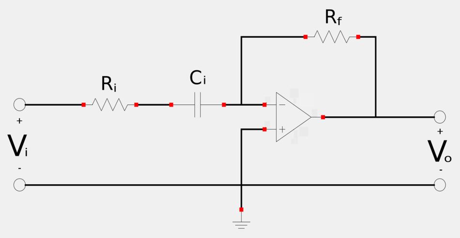
Once again, we consider equation #1 as well as the transfer function for voltage gain in order to derive the transfer function for our active high-pass filter: $$ \mathbb{H}(\omega) = \frac{\mathbb{V}_o}{\mathbb{V}_i} = \frac{-\mathbb{Z}_f}{\mathbb{Z}_i} $$ Also notice that if we compare the above schematic to the schematic for a general 1st order active filter we see that: $$ \mathbb{Z}_f = R_f $$ and: $$ \mathbb{Z}_i = R_i+\frac{1}{j\omega C_i} $$ Therefore: $$ \mathbb{H}(\omega) = \frac{-R_f}{R_i+\frac{1}{j\omega C_i}} $$ When we simplify the above expression we get:
Transfer function for an active 1st order high-pass filter:
$$ \mathbb{H}(\omega) = \frac{-j\omega C_iR_f}{1+j\omega C_iR_i} $$
Additionally, the gain of this filter is expressed as the following:
$$ gain = \frac{-R_f}{R_i} \;\;\; ,as\;\omega \rightarrow \infty \;\;(very\;high\;frequencies) $$
The corner frequency is defined as:
$$ corner\;frequency = \omega_c = \frac{1}{R_iC_i} $$
Band-Pass Filter
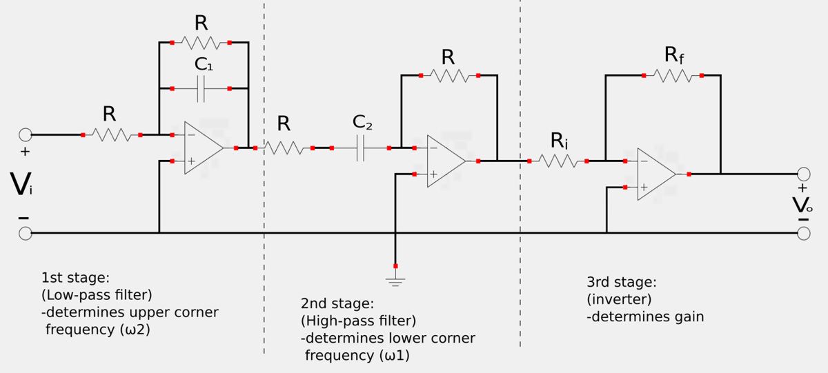
A band-pass filter can be constructed by cascading active low-pass and active high-pass filters. Furthermore, a gain (K) can be achieved over the desired range of frequencies. In this scenario, the high and low-pass filters have unity gain (1) and an inverter is used at the end of the chain to produce a gain of -Rf/Ri. The schematic representation of the band-pass filter is shown below:
Band-pass filter transfer function:
The transfer function for an active band-pass filter is found by multiplying the transfer functions of the low-pass and high-pass filter stages with the gain of the inverter stage. Note that the gain of the low-pass and high-pass filter stages is unity (1) as well as negative since they are also inverting amplifiers. $$ \mathbb{H}(\omega) = \frac{\mathbb{V}_o}{\mathbb{V}_i} $$ $$ \qquad = \frac{-R_f}{R_i} \Big( \frac{-1}{1+j \omega C_1R} \Big) \Big( \frac{-j \omega C_2 R}{1+j \omega C_2 R} \Big) $$
$$ \mathbb{H}(\omega) = \frac{-R_f}{R_i} \Big( \frac{1}{1+j \omega C_1R} \Big) \Big( \frac{j \omega C_2 R}{1+j \omega C_2 R} \Big), \quad(Eqn\;2) $$
The corner frequencies for an active band-pass filter are defined as:
$$ \omega_1 = \frac{1}{RC_2}, \qquad \omega_2 = \frac{1}{RC_1} $$
The center frequency is defined as:
$$ \omega_o = \sqrt{\omega_1 \omega_2} $$
Bandwidth:
$$ B = \omega_2 - \omega_1 $$
Quality factor:
$$ Q = \frac{\omega_o}{B} $$
Band-pass filter gain
To determine the expression for the gain of this band-pass filter, we begin by rewriting the transfer function (equation #2) in the standard form we used to construct Bode Plots: $$ \mathbb{H}(\omega) = \frac{-R_f}{R_i} \Big( \frac{1}{1+j \omega C_1R} \Big) \Big( \frac{j \omega C_2 R}{1+j \omega C_2 R} \Big), \quad(Eqn\;2) $$ $$ \qquad\; = \frac{-R_f}{R_i} \Big( \frac{\frac{1}{RC_1}}{\frac{1}{RC_1}+\frac{j\omega RC_1}{RC_1}} \Big) \Big( \frac{\frac{j\omega RC_2}{RC_2}}{\frac{1}{RC_2}+\frac{j\omega RC_2}{RC_2}} \Big) ,\quad (Eqn\;3) $$ We proceed to simplify the above expression by canceling like terms in the fractions. Additionally, recall that: $$ \omega_2 = \frac{1}{RC_1}, \qquad \omega_1 = \frac{1}{RC_2} $$ After simplifying and rewriting in terms of the corner frequencies, equation #3 becomes: $$ \mathbb{H}(\omega) = \frac{-R_f}{R_i} \Big( \frac{\omega_2}{\omega_2+j\omega} \Big) \Big( \frac{j\omega}{\omega_1+j\omega} \Big) $$ $$ \qquad\; = \frac{-R_f}{R_i} \Big( \frac{j\omega \omega_2}{(\omega_1+j\omega)(\omega_2+j\omega)} \Big) $$ In order to determine the gain, we need to find the magnitude of the transfer function at the center frequency. Therefore we proceed to substitute the expression for the center frequency into the above equation: $$ \mathbb{H}(\omega) = \frac{-R_f}{R_i} \Big( \frac{j\omega_o \omega_2}{(\omega_1+j\omega_o)(\omega_2+j\omega_o)} \Big) $$ $$ |\mathbb{H}(\omega)| = \Big|\frac{-R_f}{R_i} \Big( \frac{j\omega_2\sqrt{\omega_1 \omega_2 }}{(\omega_1+j\sqrt{\omega_1 \omega_2})(\omega_2+j\sqrt{\omega_1 \omega_2})} \Big) \Big| $$ If we simplify the above expression we get:
$$ |\mathbb{H}(\omega)| = \frac{R_f}{R_i} \Big( \frac{\omega_2}{\omega_1+\omega_2} \Big) = K = gain\;for\;passband $$
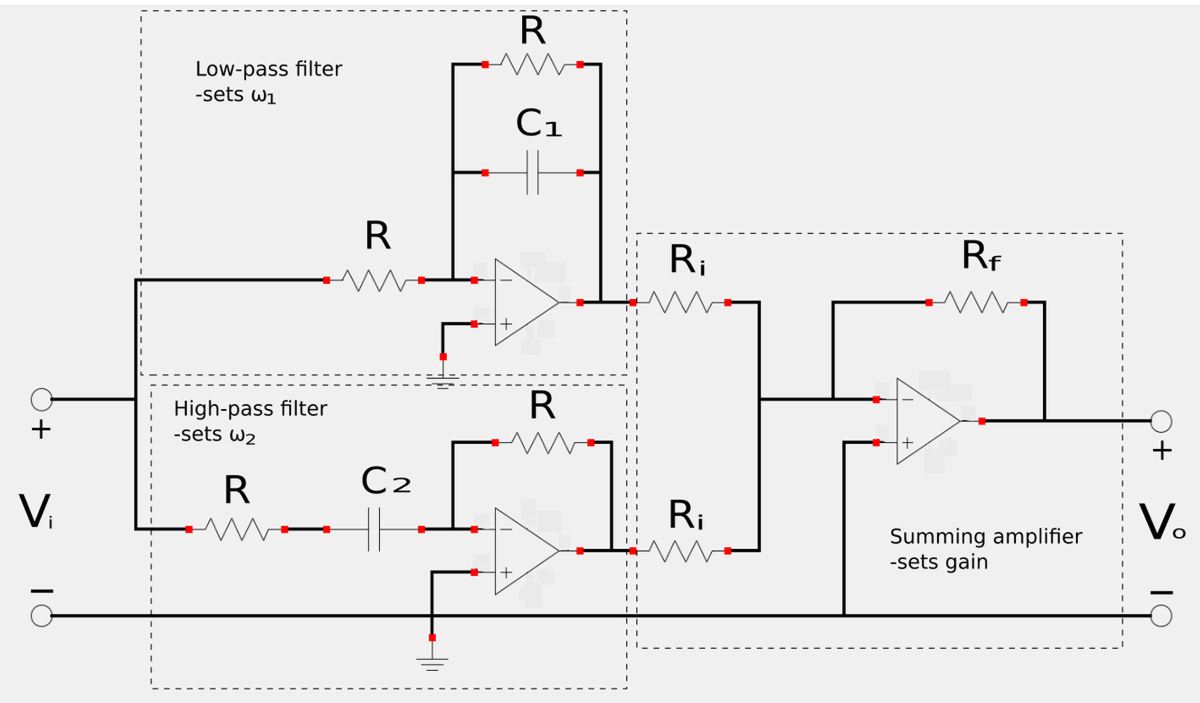
Band-Reject (Notch) Filter
A band-reject (or notch) filter is constructed via the parallel combination of an active high-pass and active low-pass filter as well as a summing amplifier which sets the gain. The notch filter schematic is shown below:
Band-reject filter transfer function:
The transfer function for a band-reject filter is found by multiplying the transfer functions for the high and low-pass filters with the gain of the inverting/summing amplifier. Since the gain is determined by the inverter, the -Rf/Ri term is omitted for the low and high-pass filter stages:
$$ \mathbb{H}(\omega) = \frac{\mathbb{V}_o}{\mathbb{V}_i} = \frac{-R_f}{R_i}\Big( \frac{-1}{1+j\omega C_1R}-\frac{j\omega C_2R}{1+j\omega C_2R} \Big) \quad,(Eqn\;4) $$
$$ \omega_1 = \frac{1}{RC_2}, \qquad \omega_2 = \frac{1}{RC_1} $$
$$ \omega_o = \sqrt{\omega_1 \omega_2} $$
Bandwidth:
$$ B = \omega_2 - \omega_1 $$
Quality factor:
$$ Q = \frac{\omega_o}{B} $$
Band-reject filter gain
To determine the gain of this filter we will again rewrite the transfer function (eqn #4) in terms of the upper and lower corner frequencies. $$ \mathbb{H}(\omega) = \frac{\mathbb{V}_o}{\mathbb{V}_i} = \frac{-R_f}{R_i}\Big( \frac{-1}{1+j\omega RC_1}-\frac{j\omega RC_2}{1+j\omega RC_2} \Big) \quad,(Eqn\;4) $$ For equation #4 we multiply by -1 and divide the 1st term inside the parenthesis by RC1 and the second term by RC2: $$ = \frac{R_f}{R_i}\Big( \frac{\frac{1}{RC_1}}{\frac{1}{RC_1}+\frac{j\omega RC_1}{RC_1}}+\frac{\frac{j\omega RC_2}{RC_2}}{\frac{1}{RC_2}+\frac{j\omega RC_2}{RC_2}} \Big) $$ $$ = \frac{R_f}{R_i}\Big( \frac{\frac{1}{RC_1}}{\frac{1}{RC_1}+j\omega}+\frac{j\omega}{\frac{1}{RC_2}+j\omega } \Big) $$ We now substitute the expressions we derived for the corner frequencies of a band-reject filter into the above expression: $$ = \frac{R_f}{R_i}\Big( \frac{\omega_2}{\omega_2+j\omega}+\frac{j\omega}{\omega_1+j\omega } \Big) $$ We now divide the first term inside the parenthesis by w2 and the second term by w1 to get the following: $$ = \frac{R_f}{R_i}\Big( \frac{1}{1+\frac{j\omega}{\omega_2}}+\frac{\frac{j\omega}{\omega_1}}{1+\frac{j\omega}{\omega_1} } \Big) $$ After grinding through the fractional math, the above expresion can be made to look like the following:
$$ \mathbb{H}(\omega) = \frac{R_f}{R_i} \Big[ \frac{1+\frac{j2\omega}{\omega_1}+\frac{(j\omega)^2}{\omega_1\omega_2}}{(1+\frac{j\omega}{\omega_2})(1+\frac{j\omega}{\omega_1})} \Big] = \frac{\mathbb{V}_o}{\mathbb{V}_i} = K = Gain \quad,(Eqn\;5) $$ Notice that as omega approaches zero and infinity, the gain becomes: $$ K = \frac{R_f}{R_i} $$ Now, recall the definition of the center frequency of a band-reject filter: $$ \omega_o = \sqrt{\omega_1 \omega_2} $$ If we substitute wo for w in equation #5 we get the following:
Gain (at center frequency) for band-reject filter:
$$ \mathbb{H}(\omega_o) = \frac{R_f}{R_i} \Big( \frac{2\omega_1}{\omega_1+\omega_2} \Big) = K $$
In the next page we will look at an active filter example problem.
Continue on to active filter example problem #1...