In regards to Bode plots,you may have noticed that the amplitude plot sometimes has a pronounced "peak". This is referred to as the "resonant peak". Any system that contains a complex pair of poles will display resonance. As a result, there is oscillation of stored energy from one form to another. Circuits that contain at least one inductor and one capacitor display resonance
Resonance (definition)
a condition in an RLC circuit where the capacitor and the inductor reactances are equal in magnitude and result in a purely resistive impedance.
Consider the following series RLC circuit (with labeled impedances):
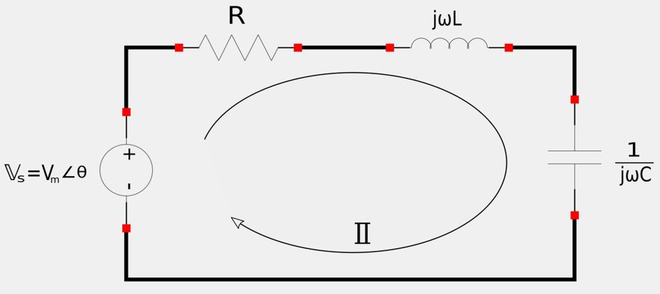
Note that the input impedance can be defined as: $$ \mathbb{Z} = \frac{\mathbb{V}_s}{\mathbb{I}} $$ ...and if you recall the four expressions for a Transfer Function you can see that $$ \mathbb{Z} = \frac{\mathbb{V}_s}{\mathbb{I}} = transfer\;impedance = \mathbb{H}_{\omega} $$ If we calculate the input impedance by adding the impedance values in series we get: $$ \mathbb{Z} = \mathbb{H}_{\omega} = R + j\omega L + \frac{1}{j\omega C} $$ or:
$$ \mathbb{Z} = \mathbb{H}_{\omega} = R+j(\omega L - \frac{1}{\omega C}) \qquad,(Eqn\;1)$$
Resonant Frequency
Up above we mentioned that resonance occurs when the circuit impedance is purely resistive. In order for this to happen in a series RLC circuit, the imaginary part of equation #1 must equal zero: $$ I_m \{ \mathbb{H}_{\omega} \} = 0 $$ $$ \omega L - \frac{1}{\omega C} = 0 $$ $$ \omega L = \frac{1}{\omega C} \qquad,(Eqn\;2) $$ The value of omega that satisfies equation #2 is known as the "resonant frequency". $$ \omega_o = resonant \; frequency $$ We now rewrite equation #2 as: $$ \omega_o L = \frac{1}{\omega_o C} $$ Solving for the resonant frequency gives us:
$$ \omega_o = \frac{1}{\sqrt{LC}} \quad,Resonant\;frequency\; in \frac{rad}{sec} $$
Knowing that: $$ \omega_o = 2\pi f_o $$ we can also calculate the resonant frequency in Hertz:
$$ f_o = \frac{1}{2\pi \sqrt{LC}} \quad,Resonant\;frequency\; in \; Hz $$
4 characteristics of the resonant frequency:
- Impedance is purely resistive $$ \mathbb{Z} = R $$ The inductor and capacitor in series act like a short circuit. (Entire source voltage is across resistor.)
- Voltage and current are in phase. Recalling the definition for the Power Factor: $$ p_f = \cos(\theta_v - \theta_i) $$ If V,I are in phase then: $$ p_f = \cos(0) = 1 = unity $$
- The magnitude of the transfer impedance, H(w) = Z, is at it's minimum value.
- Inductor and capacitor voltage values can be much larger than the source voltage: $$ V_L = \frac{V_m}{R} \omega_o L=QV_m \qquad, V_C = \frac{V_m}{R} \Big( \frac{1}{\omega_o C} \Big)=QV_m $$ ...where Q = quality factor (to be discussed shortly)
Power at Resonant Frequency and Half-Power Frequencies
Let's revisit our series RLC circuit:
Recall that phasor current can be defined as: $$ \mathbb{I} = \frac{\mathbb{V}}{\mathbb{Z}} $$ ...and the magnitude of this current is defined as: $$ |\mathbb{I}| = I = \Big| \frac{\mathbb{V}}{\mathbb{Z}} \Big| ,\qquad(Eqn\;3) $$
Recalling that: $$ \mathbb{V} = V_m\angle \theta $$ ...and by equation #1 $$ \mathbb{Z} = R+j \Big(\omega L - \frac{1}{\omega C} \Big) $$ ...we can rewrite equation #3 as:
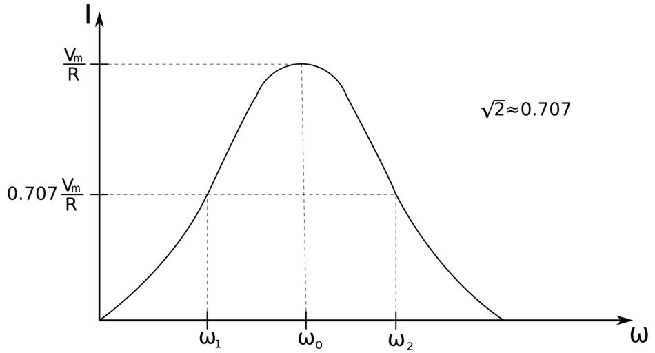
$$ I = \frac{V_m}{\sqrt{ R^2+ \Big(\omega L - \frac{1}{\omega C} \Big)^2 }} $$ Now let's look at the magnitude plot of the this current:
Power at resonant frequency:
From our discussions of average power in AC circuits, recall that the average power of a circuit where voltage and current are in-phase can be defined as: $$ P(\omega) = \frac{1}{2} I^2 R $$ From the graph above, we can deduce that the highest power dissipation will occur at the resonant frequency. At the resonant frequency, the current magnitude equals: $$ I = \frac{V_m}{R} $$ ...which means that average power at resonance is defined as: $$ P_{\omega_o} = \frac{1}{2} \Big( \frac{V_m^2}{R^2} \Big)R $$ $$ P_{\omega_o} = \frac{V_m^2}{2R} $$ This jives with our discussion on average power when voltage and current are in-phase. For this reason we have the following expressions for average power at the resonant frequency:
Average power at resonant frequency (voltage/current are in phase and impedance is purely resistive): $$ P_{\omega_o} = \frac{V_m^2}{2R} $$ $$ P_{\omega_o} = \frac{1}{2} V_m I_m $$ $$ P_{\omega_o} = \frac{1}{2} I_m^2 R $$
Half-power frequencies:
As the name suggests, half-power frequencies are frequencies where the dissipated power is 1/2 the maximum power dissipated at resonance. $$ \omega_1 = \omega_2 = half\;power \; frequencies $$ One half of the maximum power is defined as: $$ p_{\omega1} = p_{\omega2} = \frac{1}{2} \Big( \frac{V_m^2}{2R} \Big) $$
Average power at half-power frequencies: $$ p_{\omega1} = p_{\omega2} = \frac{V_m^2}{4R}$$
The half-power frequencies can be determined by the following equation: $$ |\mathbb{Z}| = \sqrt{2}R $$ $$ \sqrt{ R^2+ \Big(\omega L - \frac{1}{\omega C} \Big)^2 } = \sqrt{2}R $$ Solving for omega gives us our two half-power frequencies:
Half-power frequencies $$ \omega_1 = -\frac{R}{2L} + \sqrt{\Big( \frac{R}{2L} \Big)^2 + \frac{1}{LC}} $$ $$ \omega_2 = \frac{R}{2L} + \sqrt{\Big( \frac{R}{2L} \Big)^2 + \frac{1}{LC}} $$
If we wanted to relate half-power frequencies to the resonant frequency, we would find that:
$$ \omega_o = \sqrt{\omega_1 \; \omega_2} $$
Bandwidth (B)
The term Bandwith can have different meanings depending on the application, but here we use it to refer to the difference between the two half-power frequencies (half-power Bandwith).
Half-power bandwidth is the width of the frequency band between the half-power frequencies. $$ B = \omega_2 - \omega_1 $$
Quality Factor (Q)
The Quality Factor is effectively a measurement of the "sharpness" of the resonance peak. As we mentioned above, during resonance, reactive energy is oscillating between the inductor and capacitor. "Q" relates the maximum (or peak) energy stored to the energy dissipated per cycles of oscillation.
$$ Q = 2\pi \Big( \frac{Peak\;energy\;stored\;in\;a\;circuit}{Energy\;dissipated\;by\;circuit\;in\;one\;period\;of\;resonance} \Big) $$
For a series RLC circuit, the peak energy stored is: $$ \frac{1}{2} LI^2 $$ ...and the energy dissipated in one period is: $$ \frac{1}{2} (I^2R)\Big( \frac{1}{f_o} \Big) $$ Therefore: $$ Q = 2\pi \frac{\frac{1}{2} LI^2}{\frac{1}{2} (I^2R)\Big( \frac{1}{f_o}\Big)} $$
$$ Q = \frac{2\pi f_o L}{R} = \frac{\omega_o L}{R} = \frac{1}{\omega_o C R} $$ The Quality Factor (Q) is a dimensionless unit.
Relating Bandwidth (B) to Quality Factor (Q)
Recall our definition of Bandwith (B): $$ B = \omega_2 - \omega_1 $$ ...as well as our definitions of our two half-power frequencies: $$ \omega_1 = -\frac{R}{2L} + \sqrt{\Big( \frac{R}{2L} \Big)^2 + \frac{1}{LC}} $$ $$ \omega_2 = \frac{R}{2L} + \sqrt{\Big( \frac{R}{2L} \Big)^2 + \frac{1}{LC}} $$ If we plug in the half-power frequency equations into the equation for Bandwith we end up getting: $$ B = \frac{2R}{2L} = \frac{R}{L} \qquad,(Eqn\;4) $$ Additionally, we defined the quality factor (Q) as: $$ Q = \frac{\omega_o L}{R} $$ We can rearrange the terms of this expression to get: $$ \frac{R}{L} = \frac{\omega_o}{Q} \qquad,(Eqn\;5) $$ Substituting equation #5 into equation #4 gives us: $$ B = \frac{\omega_o}{Q} $$ We could also play around with the expressions we have derived so far to get: $$ B = \omega_o^2 CR $$ This gives us four expressions for the half-power Bandwith (B):
Expressions for half-power Bandwith (B):
$$ B = \omega_2 - \omega_1 $$ $$ B = \frac{R}{L} $$ $$ B = \frac{\omega_o}{Q} $$ $$ B = \omega_o^2 CR $$
Quality Factor (Q) and Selectivity
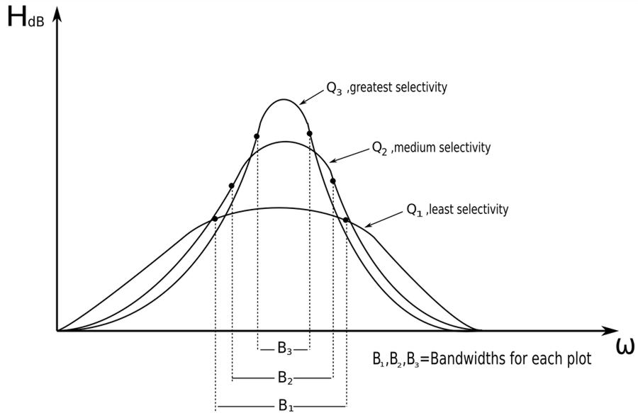
Up above we determined that: $$ B = \frac{\omega_o}{Q} $$ Rearranging terms gives us: $$ Q = \frac{\omega_o}{B} $$ For a resonant circuit, we can think of the Quality Factor as the ratio of resonant frequency to bandwith. The higher the value of Q, the smaller the bandwith and the more "selective" the circuit is.
Selectivity:
"Selectivity" is the ability of the circuit to respond to certain frequencies while discriminating against all other frequencies. To select or reject a narrow band of frequencies, "Q" must be high. On the other hand, a low value for "Q" allows for the selection of a wider band of frequencies. The magnitude plots below helps illustrate this:
Resonant circuits are designed to operate at or near their resonant frequency.
High-Q circuits:
A circuit is considered to be "high-Q" when: $$ Q \geq 10 \qquad,"High-Q \; Circuit" $$ In a high-Q circuit, the half-power frequencies are taken to be symmetrical about the resonant frequency such that: $$ \omega_1 \approx \omega_o - \frac{B}{2} $$ $$ \omega_2 \approx \omega_o + \frac{B}{2} $$
Continue on to series resonance (example problem)...