Filters are used to pass desired frequencies while rejecting (attenuating) non-desired frequencies.
- Passive filters - contain only passive elements (R,L,C)
- Active filters - contain active elements (transistors, op-amps)
Four types of passive filters:
1) Low-pass
-passes low frequencies and blocks high frequencies.
2) High-pass
-passes high frequencies and blocks low frequencies.
3) Band-pass
-passes frequencies within a frequency band while attenuating frequencies outside of the band.
4) Band-stop
-passes frequencies outside a frequency band while attenuating frequencies inside of the band.
Low-Pass Filter:
The output of a low-pass filter is taken across the capacitor of a series RC circuit (shown below):
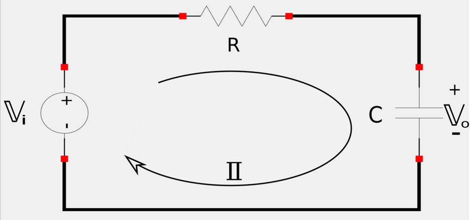
Output voltage relative to input voltage can be expressed via the following transfer function: $$ \mathbb{H}(\omega) = \frac{\mathbb{V}_o}{\mathbb{V}_i} $$ Using Ohm's Law and recalling the definition of the impedance for a capacitor, we get the following: $$ \mathbb{H}(\omega) = \frac{\mathbb{I}(\frac{-j}{\omega C})}{\mathbb{I}(R-\frac{j}{\omega C})} $$ $$ \qquad\; = \frac{-j}{\omega C} \Big( \frac{1}{R-\frac{j}{\omega C}} \Big) $$ $$ \qquad\; = \frac{-j}{R\omega C - j} $$ $$ \qquad\; = \frac{1}{j(R\omega C-j)} $$ After distributing the "j" term in the denominator of the above expression we get the following:
Transfer function for a low-pass filter:
$$ \mathbb{H}(\omega) = \frac{1}{1+jR\omega C} \qquad,(Eqn\;1) $$
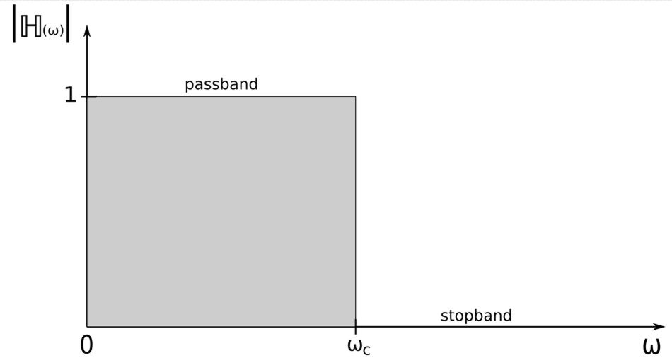
If we were to evaluate the magnitudes of this transfer function we would see that for a low-pass filter: $$ |\mathbb{H}(0)| = 1, \quad |\mathbb{H}(\infty)| = 0 $$ The Bode magnitude plot of the low-pass filter transfer function is shown below:
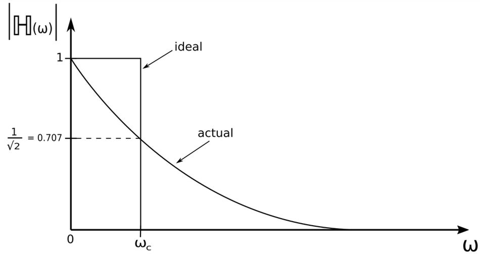
...where: $$ \omega_c = cutoff \; frequency $$ The cutoff frequency can be found by setting the magnitude of the transfer function equal to 1/sqrt(2). Therefore, we take the magnitude of equation #1 and proceed as follows: $$ |\mathbb{H}(\omega)| = \frac{\sqrt{1^2}}{\sqrt{1^2 + (R\omega C)^2}} = \frac{1}{\sqrt{2}} $$ $$ \qquad \qquad \frac{1}{\sqrt{1 + R^2 \omega^2 C^2}} = \frac{1}{\sqrt{2}} $$ $$ \qquad \qquad\quad 1 + R^2 \omega^2 C^2 = 2 $$ $$ \qquad \qquad\quad \omega^2 = \frac{1}{R^2 C^2} $$ $$ \qquad \qquad\quad \omega = \frac{1}{R C} = \omega_c $$
Cutoff frequency for low-pass filter:
$$ \omega_c = \frac{1}{R C} $$
The cutoff frequency is sometimes called the 'rolloff frequency". A low-pass filter will pass all frequencies from DC up to its cutoff frequency.
High-Pass Filter:
The output of a high-pass filter is taken across the resistor of a series RC circuit (shown below):
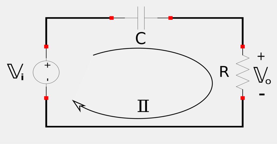
Output voltage relative to input voltage can be expressed via the following transfer function: $$ \mathbb{H}(\omega) = \frac{\mathbb{V}_o}{\mathbb{V}_i} $$ Using Ohm's Law and recalling the definition of the impedance for a capacitor, we get the following: $$ \mathbb{H}(\omega) = \frac{\mathbb{I}R}{\mathbb{I}(R+\frac{1}{j\omega C})} $$ $$ \qquad\; = \frac{R}{\frac{jR\omega C + 1}{j\omega C}} $$
Transfer function for a high-pass filter:
$$ \mathbb{H}(\omega) = \frac{jR\omega C}{1+jR\omega C} \qquad,(Eqn\;2) $$
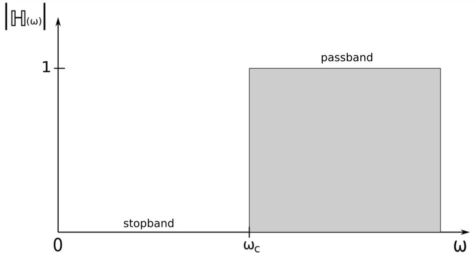
If we were to calculate the magnitude of equation #2 we would get: $$ |\mathbb{H}(\omega)| = \frac{R\omega C}{\sqrt{1+R^2\omega^2 C^2}} \qquad,(Eqn\;3) $$ Additionally, if we were to evaluate the magnitudes of this transfer function we would see that for a high-pass filter: $$ |\mathbb{H}(0)| = 0, \quad |\mathbb{H}(\infty)| = 1 $$ The Bode magnitude plot of this expression would appear as follows:
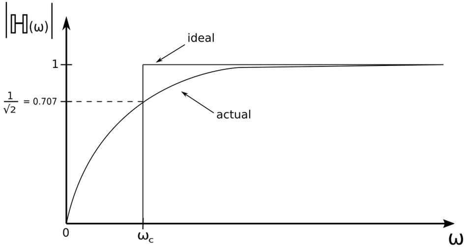
...where: $$ \omega_c = cutoff \; frequency $$ Just as with the low-pass filter, cutoff frequency for a high-pass filter can be found by setting the magnitude of the transfer function equal to 1/sqrt(2). Therefore, we take equation #3 and proceed as follows: $$ |\mathbb{H}(\omega)| = \frac{R\omega C}{\sqrt{1+R^2\omega^2 C^2}} = \frac{1}{\sqrt{2}} $$ $$ \qquad \qquad R^2\omega^2 C^2 = \frac{1+R^2\omega^2 C^2}{2} $$ $$ \qquad \qquad 2R^2\omega^2 C^2 = 1+R^2\omega^2 C^2 $$ $$ \qquad \qquad R^2\omega^2 C^2 = 1 $$ $$ \qquad \qquad \omega^2 = \frac{1}{R^2C^2} $$ $$ \qquad\qquad \omega = \frac{1}{RC} = \omega_c $$
Cutoff frequency for high-pass filter:
$$ \omega_c = \frac{1}{R C} $$ Note that it is identical for a low-pass filter.
A high-pass filter passes all frequencies above its cutoff frequency.
Band-Pass Filter:
The output of a band-pass filter is taken across the resistor of a series resonant RLC circuit (shown below):
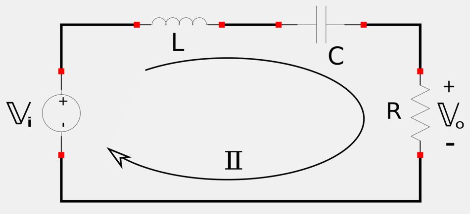
Output voltage relative to input voltage can be expressed via the following transfer function: $$ \mathbb{H}(\omega) = \frac{\mathbb{V}_o}{\mathbb{V}_i} $$ Using Ohm's Law and recalling the definitions of the impedances for a capacitor and inductor, we get the following: $$ \mathbb{H}(\omega) = \frac{\mathbb{I}R}{\mathbb{I}(R+j\omega L + \frac{1}{j\omega C})} $$
Transfer function for a band-pass filter:
$$ \mathbb{H}(\omega) = \frac{R}{R+j(\omega L - \frac{1}{\omega C})} \qquad,(Eqn\;4) $$
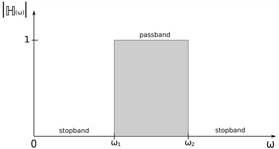
Once again we could calculate the magnitude of equation #4. If we were to do so we could determine the following expressions: $$ |\mathbb{H}(0)| = 0, \quad |\mathbb{H}(\infty)| = 0 $$ The Bode magnitude plot of this expression would appear as follows:
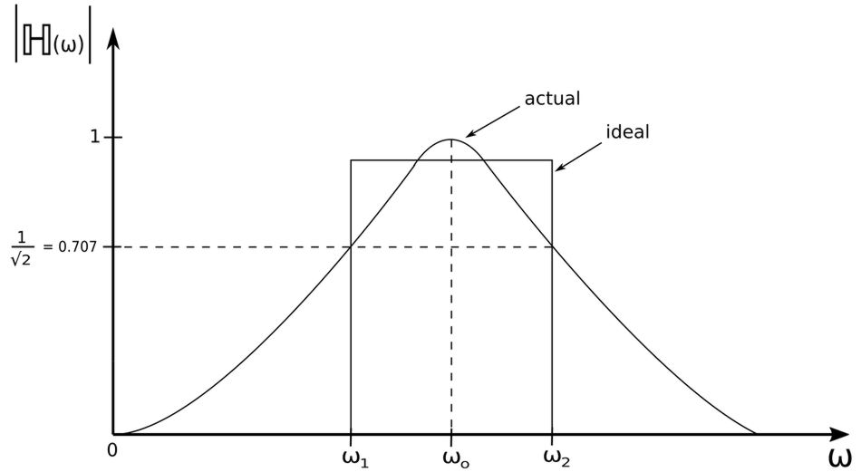
...where: $$ \omega_o = center \; frequency $$ A band-pass filter passes a band of frequencies that are centered on the center frequency and within the following range: $$ \omega_1 \lt \omega \lt \omega_2 $$ The following expression is used to determine the center frequency:
Center frequency for band-pass filter:
$$ \omega_o = \frac{1}{\sqrt{R C}} $$
You may notice that the expression for the center frequency of a band-pass filter is the same as the expression for the resonant frequency of series resonant circuit. Likewise, the expressions for bandwidth (B), Quality Factor (Q) and 1/2 power frequencies of a band-pass filter are the same as the formulas we derived in the introduction to series resonance page.
Band-pass filter formulas:
Center Frequency: $$ \omega_o = \frac{1}{\sqrt{R C}} $$ Bandwidth: $$ B = \omega_2-\omega_1 $$ $$ \;\;\; = \frac{R}{L} = \frac{\omega_o}{Q} = \omega_o^2RC $$ Quality Factor: $$ Q = \frac{\omega_oL}{R} = \frac{1}{\omega_oRC} $$ 1/2 power frequencies: $$ \omega_1 = -\frac{R}{2L} + \sqrt{\Big( \frac{R}{2L} \Big)^2 + \frac{1}{LC}} $$ $$ \omega_2 = \frac{R}{2L} + \sqrt{\Big( \frac{R}{2L} \Big)^2 + \frac{1}{LC}} $$
Band-Stop Filter:
The output of a band-stop filter is taken across the inductor-capacitor series combination of a series resonant RLC circuit (shown below):
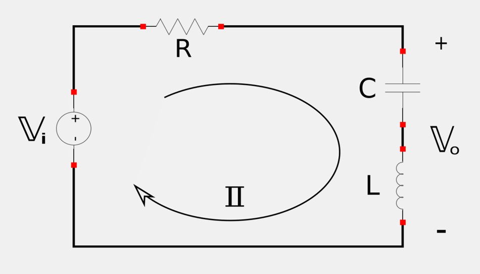
Output voltage relative to input voltage can be expressed via the following transfer function: $$ \mathbb{H}(\omega) = \frac{\mathbb{V}_o}{\mathbb{V}_i} $$ Using Ohm's Law and recalling the definitions of the impedances for a capacitor and inductor, we get the following: $$ \mathbb{H}(\omega) = \frac{\mathbb{I}(\frac{-j}{\omega C}+j\omega L)}{\mathbb{I}(R-\frac{-j}{\omega C}+j\omega L)} $$
Transfer function for a band-stop filter:
$$ \mathbb{H}(\omega) = \frac{j(\omega L-\frac{1}{\omega C})}{R+j(\omega L-\frac{1}{\omega C})} \qquad,(Eqn\;5) $$
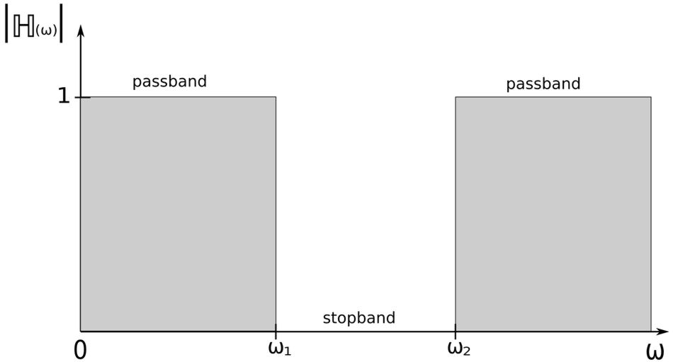
If we were to calculate the magnitude of equation #5, we would see that: $$ |\mathbb{H}(0)| = 1, \quad |\mathbb{H}(\infty)| = 1 $$ The Bode magnitude plot of this expression would appear as follows:
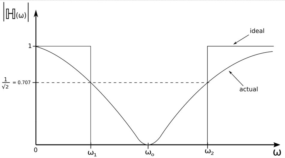
...where: $$ \omega_o = frequency \; of \; rejection $$ A band-stop filter rejects a band of frequencies that are centered on the frequency of rejection and within the following range: $$ \omega_1 \lt \omega \lt \omega_2 $$ The following expression is used to determine the frequency of rejection:
Frequency of rejection for band-stop filter:
$$ \omega_o = \frac{1}{\sqrt{R C}} $$
You may notice that the expression for the frequency of rejection for a band-stop filter is the same as the expression for the center frequency of a band-pass filter and is also the same expression used to determine the resonant frequency of series resonant circuit. Just as with a band-pass filter, the expressions for bandwidth (B), Quality Factor (Q) and 1/2 power frequencies of a band-stop filter are the same as the formulas we derived in the introduction to series resonance page.
Band-stop filter formulas:
Frequency of rejection: $$ \omega_o = \frac{1}{\sqrt{R C}} $$ Bandwidth: $$ B = \omega_2-\omega_1 $$ $$ \;\;\; = \frac{R}{L} = \frac{\omega_o}{Q} = \omega_o^2RC $$ Quality Factor: $$ Q = \frac{\omega_oL}{R} = \frac{1}{\omega_oRC} $$ 1/2 power frequencies: $$ \omega_1 = -\frac{R}{2L} + \sqrt{\Big( \frac{R}{2L} \Big)^2 + \frac{1}{LC}} $$ $$ \omega_2 = \frac{R}{2L} + \sqrt{\Big( \frac{R}{2L} \Big)^2 + \frac{1}{LC}} $$
Next we will look at a passive filter example problem:
Continue on to passive filter example problem #1...