Design a series RLC band-pass filter with cutoff frequencies of 10kHz and 11kHz. Let C=80pF and determine R,L and Q.
Determine L
Since we are given our two cutoff frequencies, we know that the center frequency will be half-way between them. $$ f_o = center \; frequency = 10.5\;kHz $$ Since most of our derived formulas involve working in radians/sec instead of hertz, let's convert the center frequency to rad/sec: $$ \omega_o = 2\pi f_o = 2\pi 10,000 $$ $$ \omega_o = 65.97\times 10^3 \; \frac{rad}{s} $$ We also know that for a band-pass filter: $$ \omega_o = \frac{1}{\sqrt{R C}} $$ Therefore: $$ \omega_o^2 = \frac{1}{LC} $$ $$ L = \frac{1}{\omega_o^2C} = \frac{1}{(65.97\times 10^3)^2(80\times 10^{-12})} $$
$$ L = 2.87\;H $$
Determine R
We also know that for a band-pass filter: $$ B = \omega_2 - \omega_1 $$ Therefore: $$ B = (11,000-10,000) \; Hz$$ $$ B = 1\; kHz $$ Converting this to rad/sec gives us: $$ B = 2\pi (1,000) $$ $$ B = (6.283\times 10^3)\frac{rad}{s} $$ Additionally, for a band-pass filter: $$ B = \frac{R}{L} $$ Therefore: $$ R = BL = (6.283\times 10^3)(2.87) $$
$$ R = 18\;k\Omega $$
Determine Q
Lastly, for a band-pass filter: $$ Q = \frac{\omega_oL}{R} $$ So, for our circuit we have: $$ Q = \frac{(65.97\times 10^3)(2.87)}{18\times 10^3} $$
$$ Q = 10.52 $$ Note that: $$ Q \geq 10 $$ Which means that this is a "High-Q circuit".
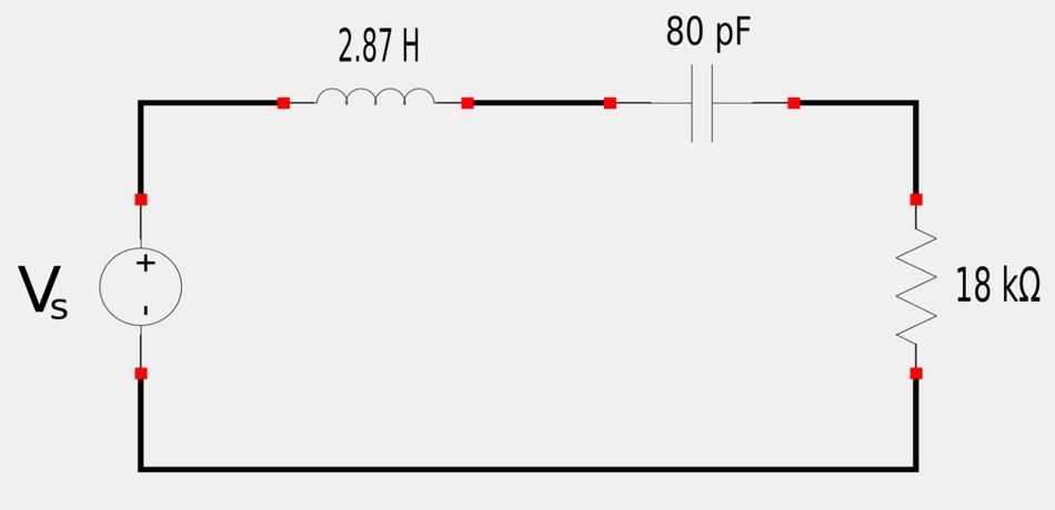
Final Circuit:
A circuit with the required cutoff frequencies given above would look like the following: