With an inverting amplifier, the non-inverting input is grounded and a voltage (Vi) is present on the inverting input through a resistor (R1). A feedback resistor (Rf) is connected between the inverting input and output. An amplifier arranged in such a manner is shown below: (Vcc and -Vcc pins have been omitted for simplification)
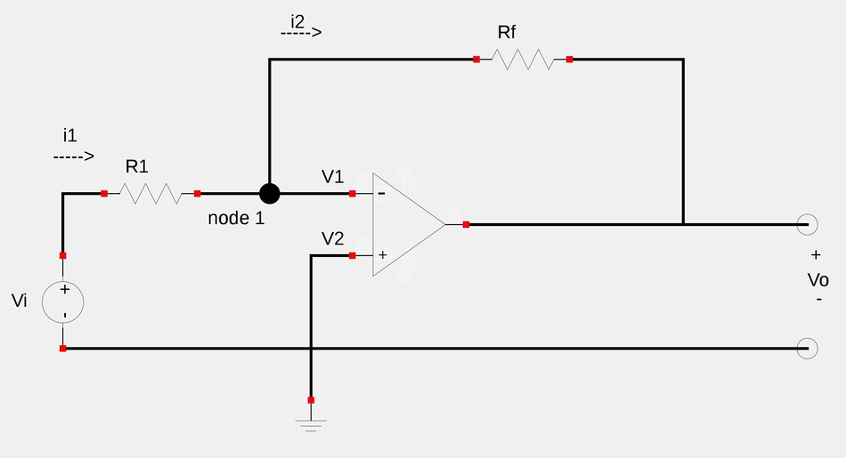
Let's try to find a relationship between the input voltage (Vi) and output voltage (Vo). Start by utilizing Kirchoff's Current Law (KCL) at node 1. $$\frac{V_i - V_1}{R_1} = \frac{V_1 - V_o}{R_f} $$ $$\frac{R_f}{R_1}(V_i-V_1) = V_1-V_o $$ $$-V_o = \frac{R_f}{R_1}(V_i-V_1) - V_1 \qquad(Eqn \; 1)$$ However, notice that V2 is grounded and therefor equal to zero. Now recall our 1st rule for ideal op-amps: $$V_1 = V_2 $$ ...which means that: $$V_1 = V_2 = 0 $$ Substituting zero for V1 in equation #1 gives us: $$-V_o = \frac{R_f}{R_1}V_i $$
Output voltage for inverting amplifier
$$V_o = \frac{-R_f}{R_1}V_i $$
Recall that in the Intro to Op-Amps page, we defined "closed loop voltage gain" as: $$A_v = \frac{V_o}{V_i} $$ Using our above definition for output voltge (Vo) of an inverting amplifier, the closed loop gain becomes: $$A_v = \frac{-R_f}{R_1}V_i \frac{1}{V_i} $$
$$A_v = \frac{-R_f}{R_1} = gain \; for \; inverting \; amplifier$$
Notice that the inverting nature of this op-amp configuration is due to the negative sign in our expression for the gain. An inverting amplifier reverses the polarity of the input signal while amplifying it. You may also notice that the gain is simply the feedback resistance divided by input resistance. This means that the gain depends only on the external elements connected to the op-amp. Let's take a look at a couple of example problems involving inverting op-amps.
Continue on to Inverting Op-Amps (example 1)...