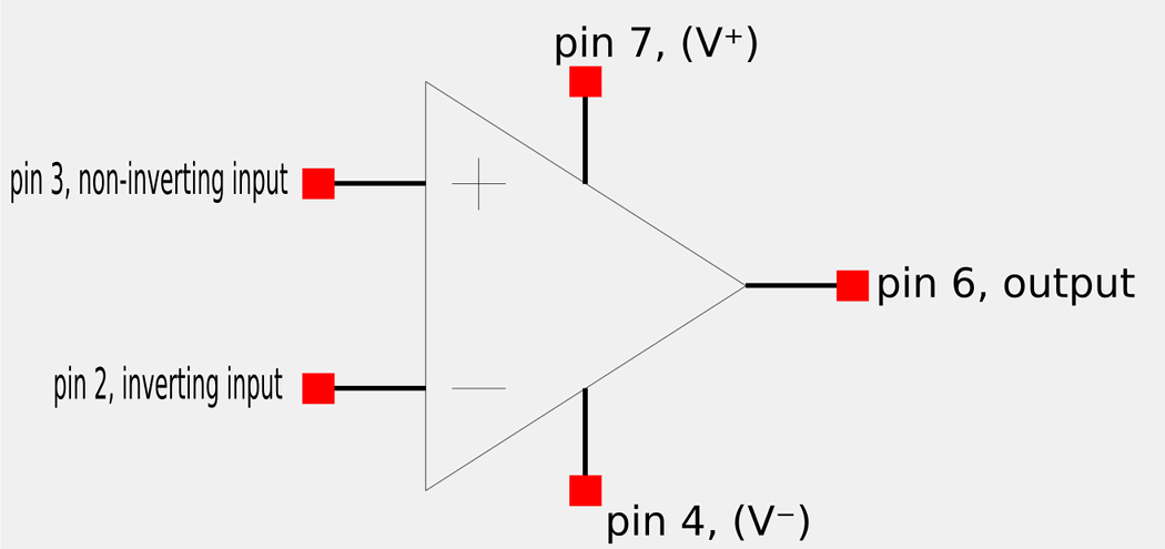
An operational amplifier (op-amp) is represented schematically below:
When it is used in an actual physical circuit it is often seen in the following 8-pin DIP package:
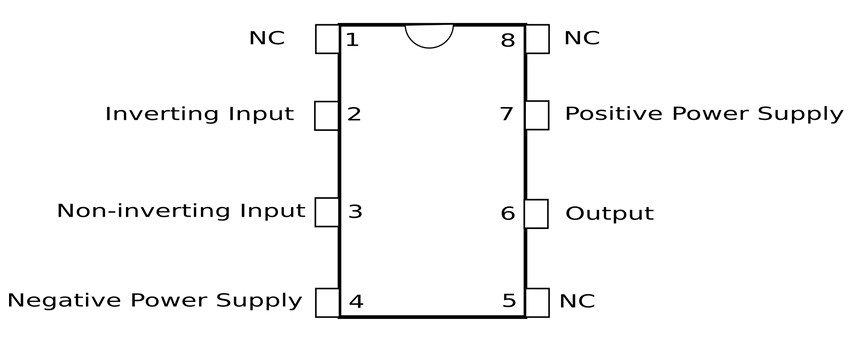
Pins number 1,5 and 8 are of no concern to us. Any input present at the non-inverting terminal will result in an output of the same polarity. Conversely, any input present at the inverting terminal will result in an output with the opposite polarity.
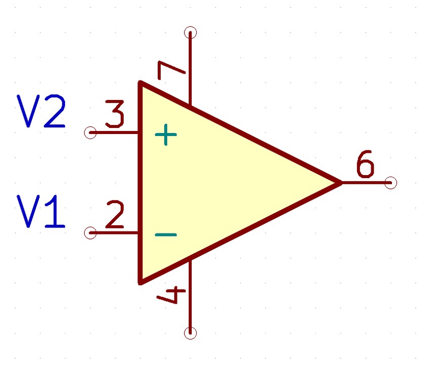
It is important to note that the voltages present on the inverting and non-inverting pins (v1 and v2 in the diagram above) are measured with respect to ground. The op-amp senses the difference between the voltage levels present on the inverting and non-inverting inputs (vd), multiplies it by a gain (A) and causes the resulting voltage to appear on the output terminal.
$$output = V_o = AV_d = A(V_2 - V_1)$$
"A" is referred to as the "open loop voltage gain" and is the gain of the op-amp without any external feedback from output to input. $$A = \frac{V_d}{V_o} = \frac{V_2 - V_1}{V_o} $$
Negative Feedback
Rather than open-loop voltage gain, it is common to control the gain through the method of "negative feedback." This is done by feeding some of the output voltage back to the inverting terminal which results in what is referred to as "closed loop gain." Closed-loop gain is the ratio of the output voltage to the voltage present on the input terminal. $$Closed \; loop \; gain = \frac{V_o}{V_i} $$ It is important to note that while the closed-loop gain can reach very high values, the output voltage will be limited by the power supply voltage present on pins 4 and 7.
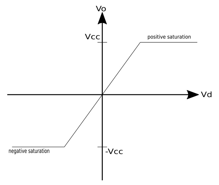
Three modes of Op-Amp Operation:
1) Positive Saturation
Positive saturation occurs when: $$V_o = V_{cc} $$ ,where Vcc is the positive voltage supply on pin #7
2) Linear Region
An op-amp operates within the linear region when the output voltage in between the voltage levels found on the positive and negative supply pins (pins #7 and 4): $$-V{cc} \leq V_o \leq V_{cc} $$
3) Negative Saturation
Negative saturation occurs when: $$V_o = -V_{cc}$$ ,where -Vcc is the positive voltage supply on pin #4
In terms of saturation, recall that output voltage is: $$V_o = AV_d $$ ...where V_d is the voltage level on the non-inverting pin minus the voltage level on the inverting pin: $$V_d = V_2 - V_1$$ If we were to increase Vd beyond the linear range, the op-amp will become saturated and yield: $$V_o = V_{cc} $$ or $$V_o = -V_{cc} $$ With this in mind, it is important to note that if we want to design op-amp circuits which behave predictably, we need to avoid the possibility of saturation by staying in the linear range of operation.
Ideal Op-Amps:
An op-amp is considered ideal if: $$1) \; open \; loop \; gain \; (A) \; = \; \infty $$ $$2) \; input \; resistance \; (R_i) \; = \; \infty $$ $$3) \; output \; resistance \; (R_o) \; = \; 0 $$
Recall that: $$V_o = AV_d $$ ...which means that: $$ A = \frac{V_o}{V_d} = \infty \quad , where \; V_d = V_2 - V_1$$ ...and when considering the 1st characteristic of an ideal op-amp we have: $$A = \frac{V_o}{V_2 - V_1} = \infty $$ In order for the above expression to be true, V2 - V1 must be zero: $$V_2 - V_1 = 0 $$ ...which gives us: $$V_2 = V_1 $$ This is our first rule for ideal op-amps.
Also note that given our three conditions for an ideal op-amp, if the input resistance is infinity (by condition #2), then the current flowing into the input pins must be zero. $$i_1 = i_2 = 0 $$ This is our second rule for ideal op-amps.
Rules for ideal op-amps:
$$1) \; V_1 = V_2 $$ $$ 2) \; i_1 = i_2 = 0 $$
The three considerations that our two rules are based on are only an approximate analysis. However, most modern amplifiers have such large gains and input impedances that it is a good approximation that will help us solve circuits involving operational amplifiers. Next we will look at one type of circuit that deals with a particular type of op-amp configuration called an "inverting amplifier."
Continue on to Inverting Op-Amps