A non-inverting op-amp is configured so that the input voltage (Vi) is applied directly to the non-inverting terminal. A resistor (R1) is connected between ground and the inverting terminal. Such a configuration is shown below:
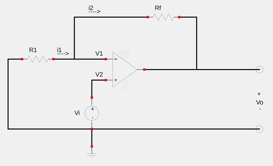
We want to determine the output voltage and gain of this setup. We start by applying Kirchoff's Current Law (KCL) at the inverting terminal.: $$i_1 = i_2 $$ $$\frac{0-V_1}{R_1} = \frac{V_1-V_o}{R_f} $$ By our first rule of ideal op-amps, we know that V1=V2. In this case, V2 is equal to Vi. Therefor, we now have: $$\frac{-V_i}{R_1} = \frac{V_i-V_o}{R_f} $$ We now proceed to solve for the output voltage (Vo) $$V_i-V_o = \frac{-R_f}{R_1}V_i $$ $$-V_o = \frac{-R_f}{R_1}V_i - V_i $$ ...and we have the:
Output voltage of a non-inverting amplifier:
$$V_o = V_i \Big( 1+\frac{R_f}{R_1} \Big)$$
We recall that the closed-loop gain is defined as: $$A_v = \frac{V_o}{V_i} $$ ...and for our current scenario this gives us: $$A_v = \frac{V_i \Big( 1+\frac{R_f}{R_1} \Big)}{V_i} $$
Voltage gain for a non-inverting amplifier:
$$A_v = 1+\frac{R_f}{R_1} $$
We note that since the gain of an inverting amplifier is positive, the output voltage will have the same polarity as the input.
Voltage follower/Unity gain amplifier:
One unique characteristic of the non-inverting op-amp occurs when the feedback resistance (Rf) is equal to zero OR is R1 is an extremely large value (equivalent to infinity). Under such circumstances, the gain is equal to 1: $$A_v = 1 $$ ...and the output voltage is equal to the input voltage: $$V_o = V_i(1) = V_i $$
Since op-amps have very high input impedances, such a voltage follower circuit is useful as a buffer to isolate one circuit from another.
Next we will take a look at an example problem involving the non-inverting amplifier.
Continue on to Non-inverting Op-Amps (example 1)...