Calculate the op-amp output voltage (Vo) for the following circuit:
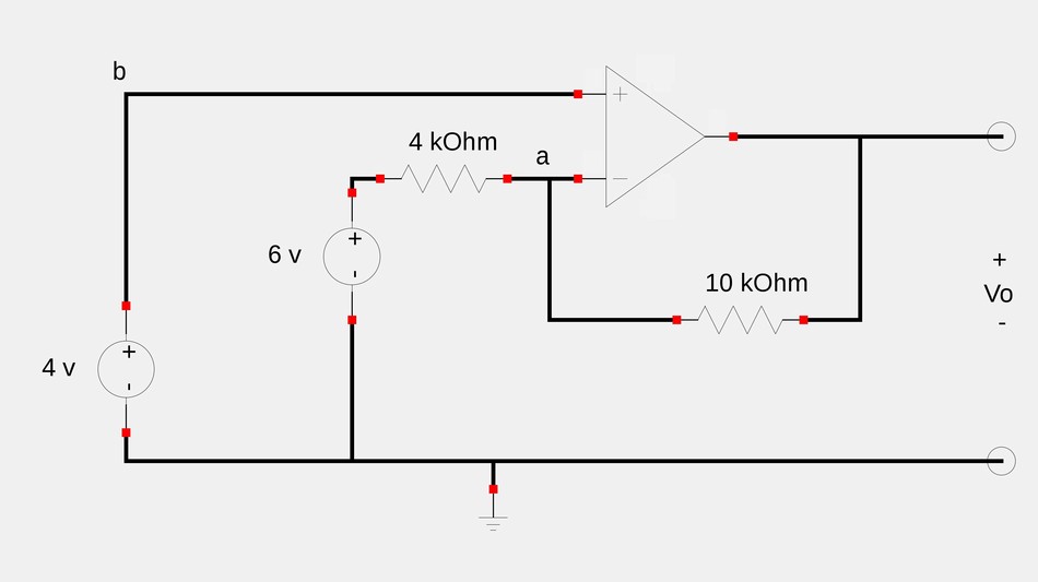
This circuit seems difficult to analyze because it doesn't appear to be either an inverting or non-inverting configuration but rather a combination of the two. We will see that there are a couple of ways to go about this circuit.
Method #1 (utilizing the principle of superposition):
The principle of superposition states that given a circuit with two or more independent sources, the voltage across (or current through) an element in a linear circuit is the sum of the voltages across (or currents through) that element due to each independent source acting alone. In order to use the superposition principle, you "turn off" all independent sources with the exception of a single source and determine the output voltage (or current) due to that single source. This step is repeated for each of the remaining independent sources. You then proceed to sum up all of the individual contributions from each source and the result is the voltage or current you originally set out to determine.
In our circuit above, the output voltage of the op-amp is the sum of the output voltage due to the 6v source acting alone and the output voltage due to the 4v source acting alone. $$V_o = V_{6v} + V_{4v}$$ We start by determining the output voltage due solely to the 6v source. The 4v source is "turned off" and the circuit appears as shown below:
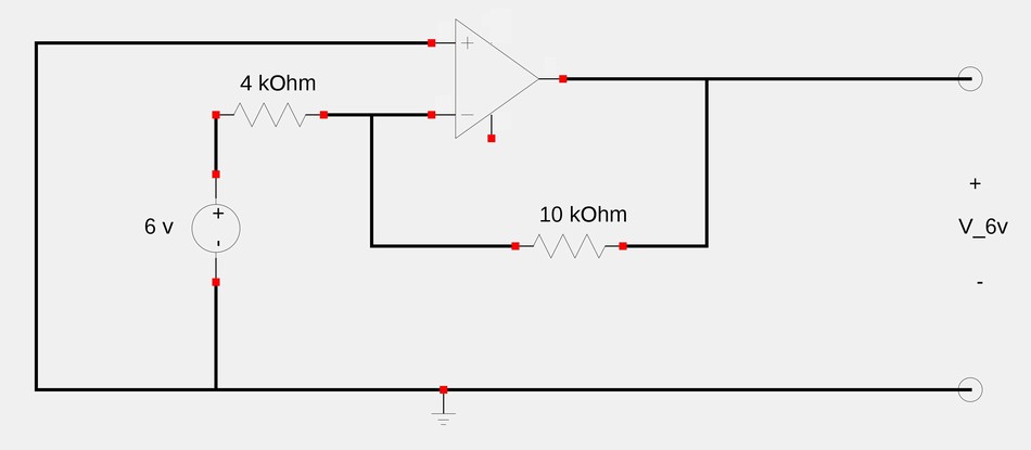
With the 4v sourced turned off, the circuit becomes an inverting amplifier with: $$ V_{6v} = \frac{-R_f}{R_1}V_i $$ ...where Rf is our 10 kOhm feedback resistor and R1 is the 4 kOhm resistor. $$V_{6v} = \frac{-10}{4}(6) = -15 \; V $$
We now determine the output voltage due solely to the 4v source. This time the 6v source is turned off and our "new" circuit is shown below:
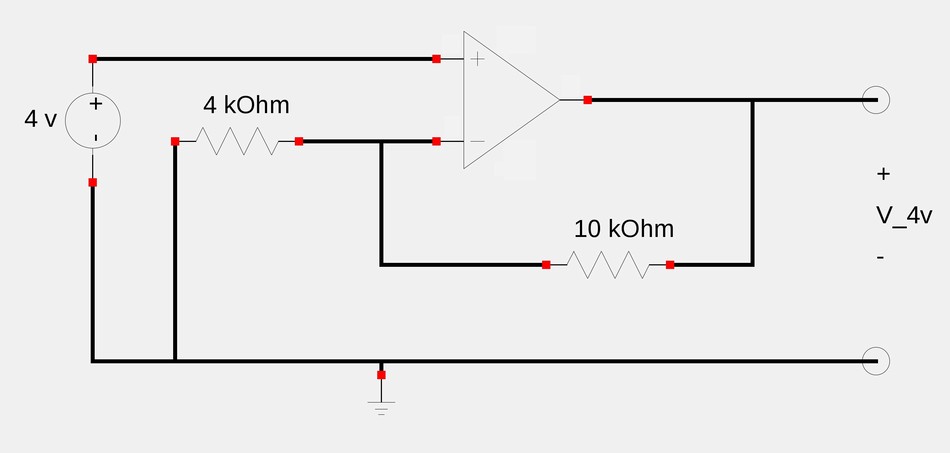
You may notice that the circuit is now a non-inverting amplifier with: $$V_{4v} = V_i \Big( 1+\frac{R_f}{R_1} \Big)$$ $$V_{4v} = 4 \Big( 1 + \frac{10}{4} \Big) = 14 \; V $$ Recall that: $$V_o = V_{6v} + V_{4v}$$ ...and in our case we have: $$V_o = -15 + 14 $$ ...which gives us a final answer of:
$$V_o = -1 \; V$$
Method #2 (Utilizing Nodal Analysis):
If we apply Kirchoff's Current Law (KCL) at node a in our original schematic, we get: $$\frac{6-V_a}{4000} = \frac{V_a-V_o}{10000} \qquad, \; (Eqn \; 1)$$ However, according to our 1st rule of ideal op-amps: $$V_a = V_b = 4 \; V $$ Substituting 4 for Va in equation #1 gives us: $$\frac{6-4}{4000} = \frac{4-V_o}{10000} $$ $$ 4-V_o = 5$$
$$V_o = -1 \; V$$ ...which is the same result we obtained using the principle of superposition in method #1