A summing amplifier combines several inputs and produces an output that is the weighted sum of the inputs. It is a variation of the inverting amplifier and is shown in the schematic below
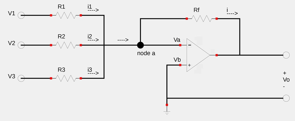
Recalling that no current enters the input pins of an op-amp and applying Kirchoff's Current Law (KCL) at node "a", we get: $$i = i_1 + i_2 + i_3 $$ $$\frac{V_a - V_o}{R_f} = \frac{V_1 - V_a}{R_1} + \frac{V_2 - V_a}{R_2} $$ $$ + \frac{V_3 - V_a}{R_3} \qquad(Eqn \; 1)$$ However, recall that the 1st rule of ideal op-amps states that: $$V_a = V_b $$ ...and since Vb=0 (it is grounded): $$V_a = 0 $$ Substituting 0 for Va in equation #1 gives us: $$\frac{- V_o}{R_f} = \frac{V_1}{R_1} + \frac{V_2}{R_2} + \frac{V_3}{R_3} $$ Solving for Vo gives us:
Output voltage of a summing amplifier:
$$V_o = - \Big[\frac{R_f}{R_1}V_1 + \frac{R_f}{R_2}V_2 + \frac{R_f}{R_3}V_3 \Big] $$
Let's take a look at an example:
Continue on to Summing Amplifier (example 1)...