The explanations in this tutorial make heavy use of the topics covered in the phasors tutorial of the "Math/Physics" section of this website. If you are rusty/unfamiliar with sinusoids, complex numbers and/or phasor notation, it is recommended that you visit those pages prior to this one. When developing the phasor relationships for the three passive components (resistors, inductors and capacitors) we will relate current and voltage and transfer the voltage-current relationship from the time domain to the frequency domain.
Developing Phasor Relationship for the Resistor:
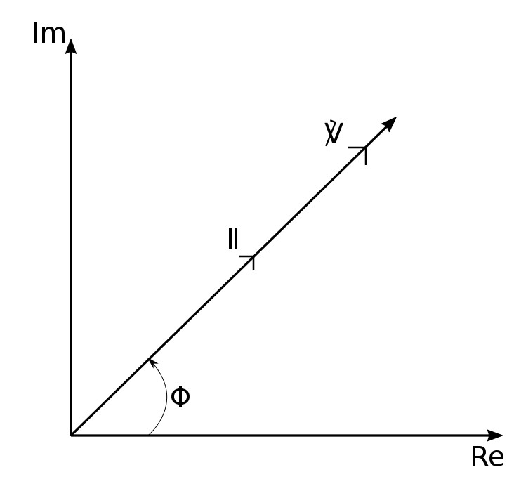
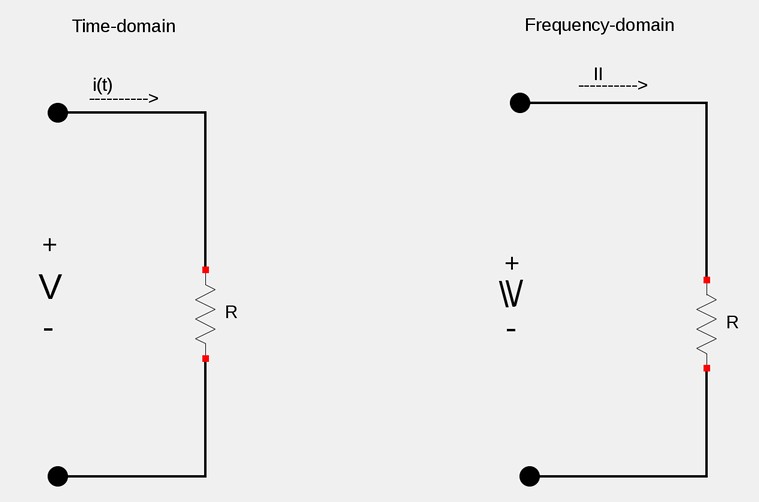
We start by taking the current through a resistor as being: $$ i = i(t) = I_m\cos(\omega t + \phi) $$ ...which when expressed in phasor notation is: $$ \mathbb{I} = I_m \angle \phi $$ In the time-domain, the voltage across a resistor is expressed as: $$ v_R = iR $$ $$ = RI_m\cos(\omega t + \phi) $$ ...which is easily converted to the frequency-domain as: $$ \mathbb{V}_R = R\mathbb{I} \;\;\;\;, (Phasor \; relationship \; for \; resistor) $$ The voltage-current relationship for the resistor in the phasor domain continues to be Ohm's Law. We also notice that voltage and current are "in-phase" for the resistor.
Developing Phasor Relationship for the Inductor:
We again start by taking the current through an inductor as being: $$ i = i(t) = I_m\cos(\omega t + \phi) $$ ...and the voltage across an inductor as being: $$ v = L\frac{di}{dt} $$ Taking the derivative of the function representing the current and plugging it into the above equation for voltage across an inductor gives us: $$ v = -LI_m\omega\sin(\omega t + \phi) \qquad(Eqn \; 1)$$ We can now use trigonometric identites to rewrite the sinusoidal equation #1 as the following positive cosine function: $$ v = \omega LI_m\cos(\omega t + \phi + 90^{\circ}) \qquad(Eqn \; 2)$$ If we rewrite equation #2 in phasor form, we get: $$ \mathbb{V}_L = \omega L I_m e^{j(\phi + 90^{\circ})} \qquad(Eqn \; 3)$$
Notice that equation #3 can be written as the following: $$ \mathbb{V}_L = \omega LI_m \angle(\phi + 90^{\circ}) \qquad(Eqn \; 4) $$
$$ \mathbb{V}_L = \omega L I_m e^{j\phi}e^{j90^{\circ}} \qquad(Eqn \; 5)$$
Note that: $$ \mathbb{I} = I_me^{j\phi} = I_m\angle\phi $$ ...and that: $$ e^{j90^{\circ}} = j $$ ...which allows us to rewrite equation #4 as:
$$ \mathbb{V}_L = j\omega L \mathbb{I} \;\;\;,(Phasor \; Relationship \; for \; an \; Inductor)$$
It is worthwhile to note that from equations 2,3 and 4 we can see that for an inductor, the voltage and current are 90 degrees out of phase. Specifically, current lags voltage by 90 degrees. (Convention gives the current phase relative to the voltage phase.)


Developing Phasor Relationship for the Capacitor:
We start by taking the voltage across a capacitor to be: $$ v = V_m\cos(\omega t + \phi) \qquad(Eqn \; 1)$$ We also recall that the current through a capacitor is defined as: $$ i_c = C \frac{dv}{dt} \qquad(Eqn \; 2)$$ Substituting equation #1 into equation #2: $$ i_c = C \frac{d}{dt} \Big( V_m\cos(\omega t + \phi) \Big) $$ $$ i_c = -CV_m \omega\sin(\omega t + \phi) \qquad(Eqn \; 3) $$ We now use trig identities to convert equation #3 to a cosine function with a positive amplitude: $$ i_c = \omega C V_m\cos(\omega t + \phi + 90^{\circ}) \qquad(Eqn \; 4)$$ We can immediately see from equation #4 that voltage and current are 90 degrees out of phase for a capacitor. Specifically, current leads voltage by 90 degrees. Rewriting equation #4 in phasor form gives us: $$ \mathbb{I}_c = \omega C V_m \angle (\phi + 90^{\circ}) $$ $$ \mathbb{I}_c = \omega C V_m e^{j(\phi + 90^{\circ})} $$ $$ \mathbb{I}_c = \omega C V_m e^{j\phi} e^{j90^{\circ}} \qquad(Eqn \; 5)$$
For equation #5, note that: $$ V_me^{j\phi} = \mathbb{V} $$ Recall Euhler's Identity: $$ e^{j\phi} = \cos\phi + j\sin\phi $$ ...and apply it to the e^j90 term in equation #5: $$ e^{j90^{\circ}} = \cos 90^{\circ} + j\sin 90^{\circ} = j $$ Substitute these two expressions into equation #5 to obtain:
$$ \mathbb{I} = cj\omega \mathbb{V} \;\;\;\;,Phasor \; Relationship $$ $$ \qquad \qquad for \; a \; Capacitor \; (current)$$
Performing simple algebra on the above expression gives us:
$$ \mathbb{V} = \frac{\mathbb{I}}{cj\omega} \;\;\;\;,Phasor \; Relationship$$$$ \qquad \qquad for \; a \; Capacitor \; (voltage)$$
While the above method adequately develops the phasor relationship for a capacitor, alternatively we can use "Expression A" from the phasors and sinusoidal calculus page which states that: $$ \frac{dv}{dt} \iff j\omega \mathbb{V} \qquad(Expression \; A)$$ Plugging expression A into equation #2 would quickly give us the phasor relationship for current through a capacitor from which we could also derive the voltage phasor.
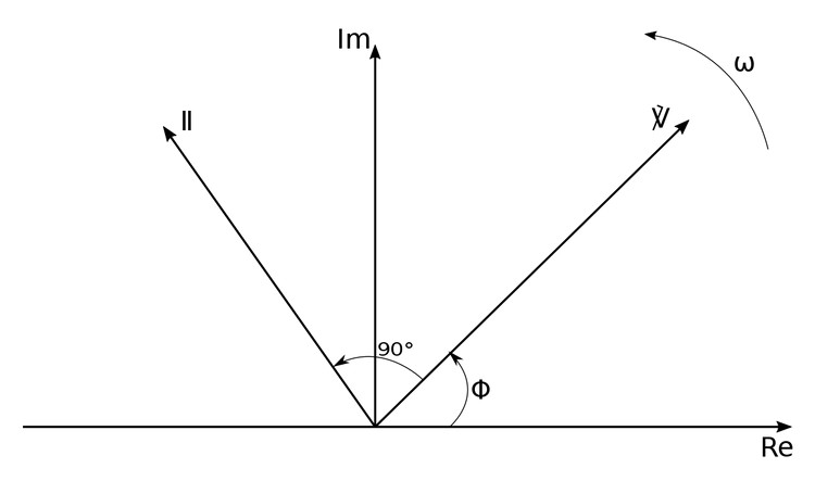
From the following phasor diagram, we can see that current leads voltage by 90 degrees for a capacitor:
Summary of voltage-current relationships for three passive circuit elements:
| Element | Time-domain | Frequency-domain |
|---|---|---|
| Resistor (R) | $$ V = Ri $$ | $$ \mathbb{V}_R = R\mathbb{I} $$ |
| Inductor (L) | $$ V = L\frac{di}{dt} $$ | $$ \mathbb{V}_L = j\omega L \mathbb{I} $$ |
| Capacitor (C) | $$ i = C\frac{dv}{dt} $$ | $$ \mathbb{V}_c = \frac{\mathbb{I}}{j\omega C} $$ $$ \mathbb{I} = cj\omega\mathbb{V} $$ |
Now that we have developed an understanding of the voltage-current relationship for resistors, inductors and capacitors (in the frequency domain), we will next look at the concepts of impedance and admittance.
Continue on to Impedance and Admittance.