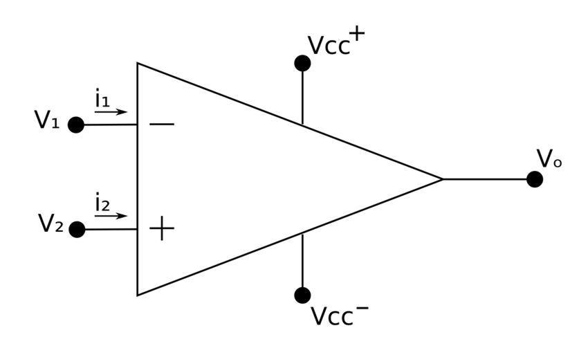
Before beginning to discuss AC op-amp circuits, it is assumed that you are already familiar with DC op-amp circuits. Some of what we discuss here is a review of the material covered in the DC op-amp pages. Start by recalling the schematic representation of an operational amplifier:
As long as the op-amp is operating in the linear region, an op-amp AC circuit can be analyzed using the same steps as other AC circuits:
- Transform the circuit to the phasor/frequency domain.
- Solve the problem using circuit techniques (nodal/mesh analysis, superposition etc...)
- Transform the resulting phasor to the time domain if desired.
Operating within the linear region:
Referring to the above schematic representation of an op-amp, let: $$ V_d = V_2 - V_1 $$ If we were to increase Vd beyond the linear range, the op-amp becomes saturated and yields: $$ V_o = V_{cc^+} \; or \; V_o = V_{cc^-} $$ Most op-amp circuits require operation to be within the linear range for predictable outputs. Therefore the linear range is defined by: $$ V_{cc^-} \le V_o \le V_{cc^+} $$
Rules for ideal op-amps:
The "ideal" op-amp model is used to solve op-amp circuits. We won't go into this any further than simply stating the two rules. Once again refer back to the DC op-amp pages for more information. In reference to the schematic at the top of the page, the two rules for an ideal op-amp are:
$$1) \; V_1 = V_2 $$ $$ 2) \; i_1 = i_2 = 0 $$
Let's take a look at an example:
Continue on to AC op-amp circuits example 1