Thevenin and Norton equivalent circuits can be applied to AC circuits in a manner similar to how they are applied to DC circuits. You may already know that the idea behind Thevenin and Norton circuits is that any linear, two terminal circuit can be replaced with an equivalent circuit consisting of either a voltage source in series with a resistor (Thevenin circuit) OR a current source in parallel with a resistor (Norton circuit). With AC circuits we simply replace "resistor" with "impedance" and recognize that we will be dealing with phasors and complex quantities.
Thevenin Equivalent Circuit:
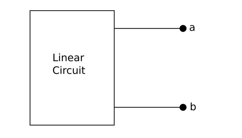
A Thevenin equivalent circuit means that we can express any linear two-terminal AC circuit (depicted below):
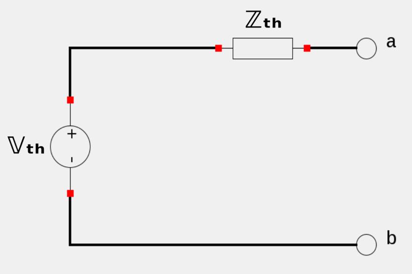
...as a voltage source in series with an impedance (as seen below):
Norton Equivalent Circuit:
A Norton equivalent circuit means that we can express any linear two-terminal AC circuit (depicted below):
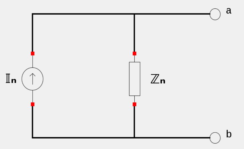
...as a current source in parallel with an impedance (as seen below):
For Thevenin and Norton circuits, the following relationships hold true: $$ \mathbb{V}_{th} = \mathbb{Z}_n \mathbb{I}_n $$ $$ \mathbb{Z}_{th} = \mathbb{Z}_n $$
Steps to determine a Thevenin or Norton Equivalent Circuit:
- Determine the open-circuit voltage across terminals a-b. OR:
- Determine the short-circuit current through terminals a-b. (Choose whichever is easiest for steps 1,2)
- Determine the equivalent impedance at terminals a-b when independent sources are "turned off". (Do not "turn off" dependant sources.)
- Solve for the unknown using Ohm's Law $$ \mathbb{Z}_{th} = \mathbb{Z}_n = \frac{\mathbb{V}_{th}}{\mathbb{I}_n} $$
For the above steps you notice that you can't "turn off" dependant souces in step #3. When dependant sources are present you must follow a unique approach to determine the equivalent impedance. This approach is outlined below
Determining Thevenin/Norton equivalent impedance for a circuit with dependent sources:
- "Turn off" independent souces.
- Apply a "dummy voltage" at terminals a-b: $$ Ex: \; \mathbb{V}_o = 1 \; V $$
- Determine the resulting current (IIo) flowing out of the dummy source:
- Equivalent Impedance becomes: $$ \mathbb{Z}_{th} = \mathbb{Z}_n= \frac{\mathbb{V}_o}{\mathbb{I}_o} $$
$$ OR: $$
- "Turn off" independent souces.
- Apply a "dummy current" at terminals a-b: $$ Ex: \; \mathbb{I}_o = 1 \; A $$
- Determine the resulting voltage (Vo) across terminals a-b:
- Equivalent Impedance becomes: $$ \mathbb{Z}_{th} = \mathbb{Z}_n= \frac{\mathbb{V}_o}{\mathbb{I}_o} $$
Now that we have a basic understanding of Thevenin and Norton equivalent circuits, let's take a look at an example problem.
Continue on to Thevenin and Norton circuits example 1