Before discussing phase-shifting circuits, let's briefly review the concepts of voltage and current division for phasors. Without going through the proofs, it is simply the same as for resistors in DC circuits.
Voltage and Current division in the frequency domain:
Voltage Division:
Consider the following circuit in the frequency domain with the labeled impedances for two circuit elements:

Just as with resistors (which isn't discussed here) the individual phasor voltages are as follows:
$$ \mathbb{V}_1 = \Big( \frac{\mathbb{Z}_1}{\mathbb{Z}_1 + \mathbb{Z}_2} \Big) \mathbb{V} \qquad , \qquad \mathbb{V}_2 = \Big( \frac{\mathbb{Z}_2}{\mathbb{Z}_1 + \mathbb{Z}_2} \Big) \mathbb{V} $$
Current Division:
Now consider the following circuit in the frequency domain with the labeled impedances for two circuit elements:
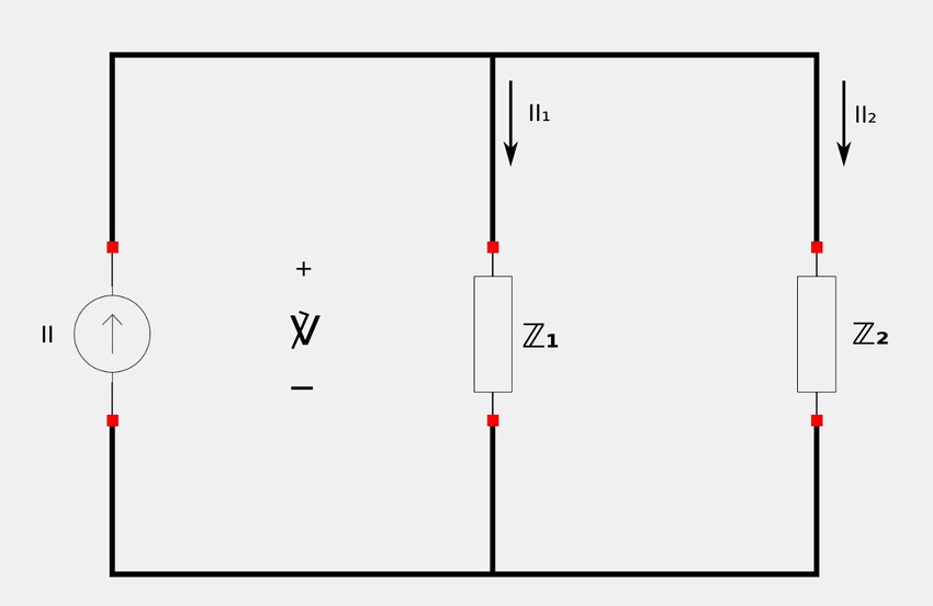
Once again, just as with resistors, the current division principle applies here. The individual phasor currents are as follows:
$$\mathbb{I}_1 = \Big( \frac{\mathbb{Z}_2}{\mathbb{Z}_1 + \mathbb{Z}_2} \Big) \mathbb{I} \qquad , \qquad \mathbb{I}_2 = \Big( \frac{\mathbb{Z}_1}{\mathbb{Z}_1 + \mathbb{Z}_2} \Big) \mathbb{I} $$
RC Phase-shifting Circuits:
Phase shifting circuits are used to correct an undesirable phase-shift (or produce a desired one.) In the Impedance and Admittance tutorial, we discussed the concept of impedance as expressed in rectangular form and learned that when the reactance is capacitive in nature, current leads the applied voltage. Therefore, using a capacitor in a circuit does the same. However, depending on whether we measure the voltage across the resistor or the voltage across the capacitor, we can obtain leading or lagging voltages (with respect to the input voltage). Consider the following RC series circuit where the output voltage is taken across the resistor:
Circuit "A"
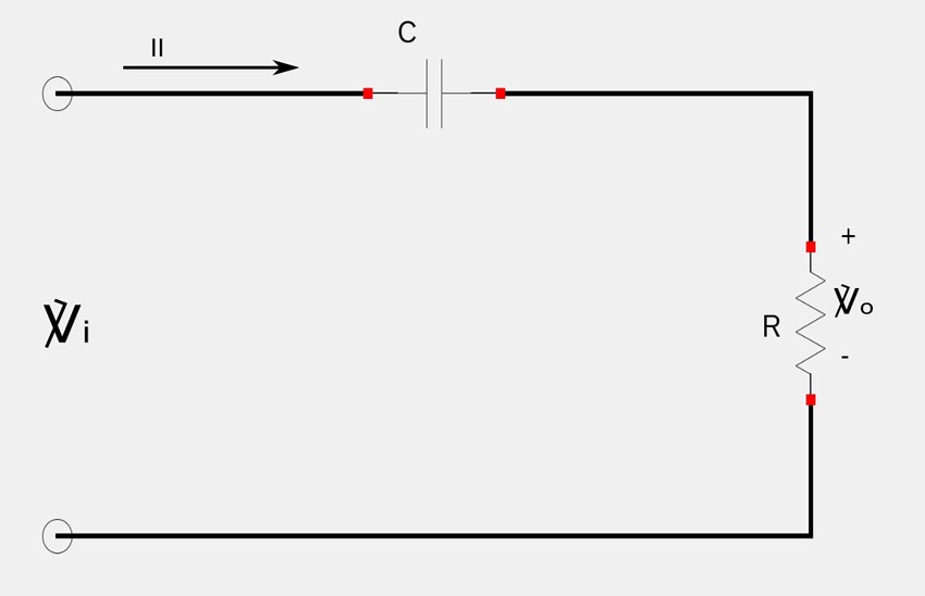
Due to the capacitor, the circuit phasor current (II) leads the applied voltage (Vi) by some phase angle (theta) where: $$ 0 \lt \theta \lt 90^{\circ} $$ Recall from the Impedance and Admittance tutorial that: $$ \mathbb{Z}_{tot} = R \pm jX $$ ... where X is the reactance. In the case of our circuit, the reactance is capacitive in nature such that: $$ X = X_c = capacitive \; reactance $$ Also recall from the same Impedance tutorial that when reactance is capacitive in nature, it is associated with a "-j" term. This means that we no have: $$ \mathbb{Z}_{tot} = R - jX \qquad(Eqn \; 1)$$ If we were to graph equation #1 on the complex plane, we would get a phase angle of: $$ \theta = tan^{-1} \Big( \frac{X_c}{R} \Big) = phase \; shift \qquad(Eqn \; 2)$$
From the Impedance and Admittance tutorial recall that: $$ \mathbb{Z}_c = \frac{-j}{\omega C} $$ and that: $$ X_c = capacitive \; reactance = I_m \{ \mathbb{Z}_c \} $$ therefore: $$ X_c = \frac{-1}{\omega C} $$ Substituting this value for Xc into equation #2 gives us the:
Phase Shift
$$ \theta = tan^{-1} \Big( \frac{-1}{R\omega C} \Big) $$
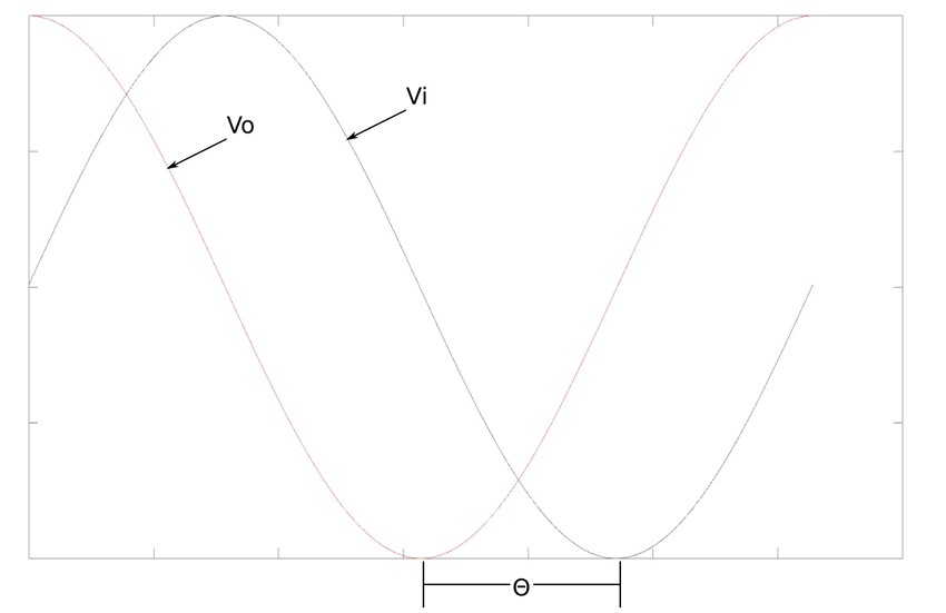
As we can see, the amount of phase shift depends on the values of R, C as well as the operating frequency of the circuit. We already learned that the voltage across a resistor is in phase with the current and as a result, Vo "leads" Vi and results in a "positive" phase shift (leading output) as seen below:
Now consider the same circuit with the output voltage taken across the capacitor (as opposed to the resistor)
Circuit "B"
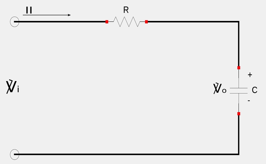
The circuit current still leads the input voltage by a phase angle of theta. However in this case, the output voltage (across capacitor) lags the input voltage and results in a "negative" phase shift as seen below:
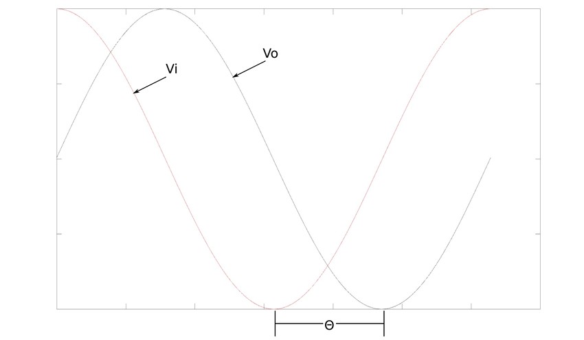
One important thing to keep in mind with a simple phase shifting circuit such as the one above is that it also acts as a voltage divider and as such the following occurs: $$ as: \theta \rightarrow 90^{\circ}, \mathbb{V}_o \rightarrow 0 $$ For this reason, if the phase shift is going to be greater than 60 degrees, simple RC circuits are chained together and: $$ \theta_{total} = sum \; of \; individual \; shifts $$ Since successive stages of shifts will load down previous stages, op-amps can be used to separate the individual stages.
Next we will look at some example problems that involve phase shifting circuits.
Continue on to phase-shifting circuits (example problem #1.)