While a battery is a common method of producing a DC source, op-amps can be used to produce AC. This is done by means of an oscillator. An oscillator is a circuit the generates AC wave-forms when given a DC input. Before examining such a circuit, let's first learn about something called the Barkhausen Criteria.
Barkhausen Criteria:
Without going into the detailed math involved with the criteria, simply understand that it is composed of two rules which must be followed for oscillations to be sustained:
- The overall gain of the oscillator must be unity (1) or greater. (Any loses must be compensated with an amplifying device.)
- The overall phase shift must be zero or an integer multiple of 2pi. (From input to output and back to input.)
Three common types of sine-wave oscillators:
- Phase-shift
- Twin T
- Wien-bridge
Our focus here will be on the Wien-bridge oscillator.
Wien-bridge Oscillator:
This oscillator is used to produce sinusoids with frequencies under 1 MHz. It is essentially an RC op-amp circuit consisting of a non-inverting amplifier with two feedback paths. Such a circuit is shown below:
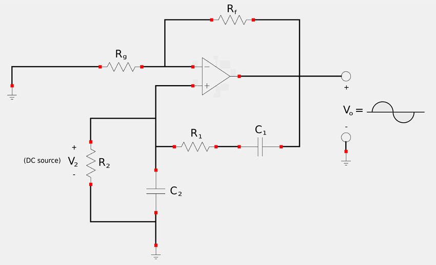
The positive feedback path (to the non-inverting input) is used to created the oscillations. The negative feedback path (to the inverting input) is used to control the gain of the amplifier.
Start by defining Zs as the impedance of the series combination of R1 and C1: $$ \mathbb{Z}_s = R_1 - \frac{j}{\omega C_1} $$ ...and Zp as the impedance of the parallel combination of R2 and C2: $$ \mathbb{Z}_p = \frac{1}{\frac{1}{R_2}+\frac{1}{\frac{-j}{\omega C_2}}} $$ $$ = \frac{1}{\frac{1}{R_2}+j\omega C_2} $$ $$ = \frac{1}{\frac{1+j\omega C_2 R_2}{R_2}}$$ $$ \mathbb{Z}_p = \frac{R_2}{1+j\omega R_2 C_2} $$ Next, recognize that the feedback voltage present on the non-inverting input is V2. Therefore the feedback ratio for the oscillating part of our circuit is: $$ feedback \; ratio = \frac{\mathbb{V}_2}{\mathbb{V}_o} = \frac{\mathbb{Z}_p}{\mathbb{Z}_s + \mathbb{Z}_p} $$ $$ = \Big( \frac{R_2}{1+j\omega R_2 C_2} \Big) \Big( \frac{1}{(R_1 - \frac{j}{\omega C_1}) + (\frac{R_2}{1+j\omega R_2 C_2})} \Big) $$ $$ \frac{\mathbb{V}_2}{\mathbb{V}_o} = \frac{\omega R_2 C_1}{\omega(R_2 C_1+R_1 C_1 + R_2 C_2) + j(\omega^2 R_1 C_1 R_2 C_2 - 1)} \qquad, Eqn \; 1$$ In order to satisfy the second Barkhausen criterion, V2 must be in phase with Vo. For this to happen, equation #1 must be purely real which means that the imaginary part of the denominator must equal zero. From here on out we will label omega as omega_o since it will represent the oscillating frequency of our output: $$ \omega_o^2 R_1 C_1 R_2 C_2 - 1 = 0 $$ $$ \omega_o^2 = \frac{1}{R_1 C_1 R_2 C_2} $$ $$ \omega_o = \frac{1}{\sqrt{R_1 C_1 R_2 C_2} } = oscillator \; freq \; in \; \frac{rad}{sec}$$ In most practical circuits, R1 = R2 = R and C1 = C2 = C. Therefore: $$ \omega_o = \frac{1}{\sqrt{R^2 C^2}} = \frac{1}{RC} \qquad,Eqn \; 2 $$ Recall that in terms of frequency and angular frequency: $$ \omega = 2\pi f $$ $$ f = \frac{\omega}{2\pi} $$ Therefore (using our above expression for omega) we have: $$ f_o = \frac{1}{2\pi RC} = oscillator \; freq \; in \; hertz $$
Substitute eqn #2 and R1 = R2 = R as well as C1 = C2 = C into eqn #1:
$$ \frac{\mathbb{V}_2}{\mathbb{V}_o} = \frac{ (\frac{1}{RC})(RC) }{\frac{1}{RC}(RC+RC+RC)+j(\frac{1}{R^2C^2}RCRC-1 ) } $$ $$ = \frac{1}{\frac{1}{RC}(3RC)+j(1-1)} $$ $$ \frac{\mathbb{V}_2}{\mathbb{V}_o} = \frac{1}{3} $$ $$ \frac{\mathbb{V}_o}{\mathbb{V}_2} = 3 $$ Here we note that in order to satisfy the 1st Barkhausen criterion, the op-amp must provide a gain of three (or higher) in order to sustain the oscillations. Recall that for a non-inverting amplifier, gain is defined as: $$ \frac{\mathbb{V}_o}{\mathbb{V}_i} = 1 + \frac{R_f}{R_g} $$ In our case, Vi=V2 and the gain must equal 3 (or greater). Therefore we have: $$ \frac{\mathbb{V}_o}{\mathbb{V}_2} = 1 + \frac{R_f}{R_g} \geq 3 $$ ...which leaves us with: $$ R_f \geq 2R_g $$
Conclusion:
In summary, we now know that for the Wien-bridge circuit depicted above, if we let: $$ R1 = R2 = R $$ and: $$ C1 = C2 = C $$ ...sine-wave oscillations will be sustained if: $$ R_f \geq 2R_g $$ ...and the frequency of the oscillations will be: $$ f_o = \frac{1}{2\pi RC} $$
Let's now take a look at an example problem of using an op-amp to produce an oscillating output:
Continue on to op-amp oscillators example problem...