A transformer is a circuit device that takes advantage of the principle of mutual inductance. They generally have 4 (or more) terminals and consist of two or more magnetically coupled coils. The two coils are often referred to by the terms "primary winding" and "secondary winding".
- Primary winding = coil connected to voltage source.
- Secondary winding = coil connected to the load.
With a linear transformer, the coils are wound on a material that has a constant magnetic permeability (ie: air, plastic, wood etc..). They are sometimes referred to as "air-core" transformers.
Input Impedance and Reflected Impedance:
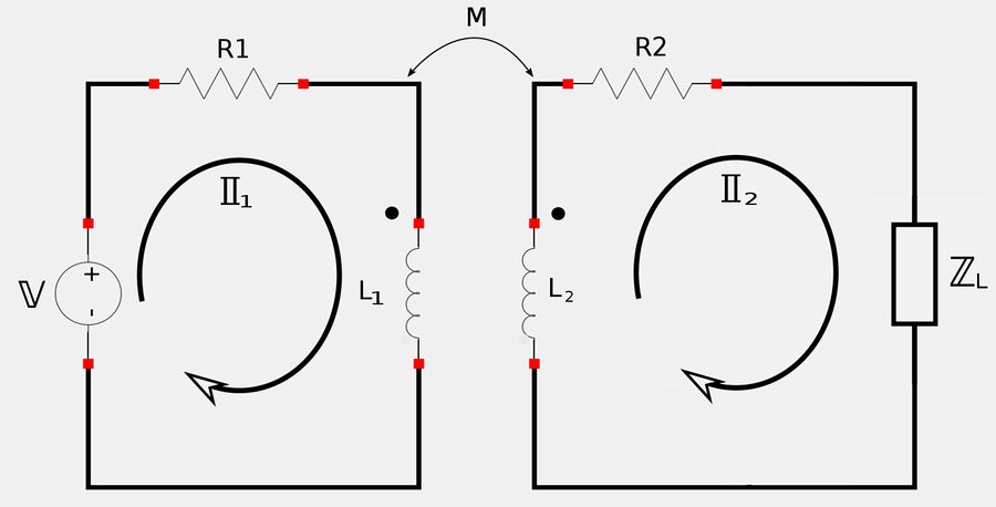
If we apply Kirchhoff's Voltage Law (KVL) to the left loop we get: $$ -\mathbb{V} + \mathbb{I}_1 R_1 + \mathbb{I}_1 j\omega L_1 - j\omega M \mathbb{I}_2 = 0 $$ $$ \mathbb{I}_1 (R_1 + j\omega L_1) - j\omega M \mathbb{I}_2 = \mathbb{V} \qquad, (Eqn \; 1) $$ Applying KVL to the right loop gives us: $$ -j\omega M \mathbb{I}_1 + \mathbb{I}_1 j\omega L_2 + \mathbb{I}_2 R_2 + \mathbb{I}_2 \mathbb{Z}_L = 0 $$ $$ -j\omega M \mathbb{I}_1 + \mathbb{I}_2 (R_2 + j\omega L_2 + \mathbb{Z}_L) = 0 \qquad,(Eqn \; 2) $$ For equation #2, let's get I2 in terms of I1: $$ \mathbb{I}_2 = \frac{j\omega M \mathbb{I}_1}{R_2 + j\omega L_2 + \mathbb{Z}_L} \qquad, (Eqn \; 3) $$ Now substitute equation #3 into equation #1: $$ \mathbb{V} = \mathbb{I}_1(R_1+j\omega L_1) - j\omega M \Big( \frac{j\omega M \mathbb{I}_1}{R_2 + j\omega L_2 + \mathbb{Z}_L} \Big) $$ $$ \;\; = \mathbb{I}_1(R_1+j\omega L_1) + \frac{\omega^2 M^2 \mathbb{I}_1}{R_2 + j\omega L_2 + \mathbb{Z}_L} $$ $$ \mathbb{V} = \mathbb{I}_1 \Big( R_1+j\omega L_1 + \frac{\omega^2 M^2}{R_2 + j\omega L_2 + \mathbb{Z}_L} \Big) $$ We can now express the input impedance as: $$ \mathbb{Z}_{in} = \frac{\mathbb{V}}{\mathbb{I}_1} = \frac{\mathbb{I}_1 \Big( R_1+j\omega L_1 + \frac{\omega^2 M^2}{R_2 + j\omega L_2 + \mathbb{Z}_L} \Big)}{\mathbb{I}_1} $$
Input Impedance
$$ \mathbb{Z}_{in} = R_1+j\omega L_1 + \frac{\omega^2 M^2}{R_2 + j\omega L_2 + \mathbb{Z}_L} \qquad,(Eqn \; 4) $$
Notice that the expression for input impedance consists of two parts: $$ 1) Primary \; impedance = R_1+j\omega L_1 $$ $$ 2) Reflected impedance = \mathbb{Z}_R = \frac{\omega^2 M^2}{R_2 + j\omega L_2 + \mathbb{Z}_L} $$ Reflected impedance is due to the coupling between the primary and secondary windings of the transformer. It acts as an impedance that is "reflected" back to the primary.
Τ Equivalent Circuits:
Τ-equivalent circuit:
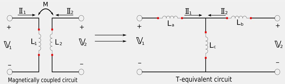
Our goal is to obtain three expressions that will allow determine inductor values for the Τ-equivalent circuit that are derived from the magnetically-coupled circuit.
Apply KVL to both loops of the magnetically coupled circuit:
For the left loop we would get the following expression: $$ \mathbb{I}_1 j\omega L_1 + \mathbb{I}_2 j\omega M = \mathbb{V}_1 $$ ...and for the right loop we would get the following: $$ \mathbb{I}_1 j\omega M + \mathbb{I}_2 j\omega L_2 = \mathbb{V}_2 $$ If we were to put the above two expressions in matrix form we would get: $$ \begin{pmatrix} j\omega L_1&j\omega M\\ j\omega M&j\omega L_2\\ \end{pmatrix} \begin{pmatrix} \mathbb{I}_1\\ \mathbb{I}_2\\ \end{pmatrix} = \begin{pmatrix} \mathbb{V}_1\\ \mathbb{V}_2\\ \end{pmatrix} \qquad ,(matrix \; eqn \; 1) $$
Apply KVL to both loops of the Τ-equivalent circuit:
For the left loop we would get the following expression: $$ \mathbb{I}_1 (j\omega L_a + j\omega L_c) + \mathbb{I}_2 j\omega L_c = \mathbb{V}_1 $$ ...and for the right loop we would get: $$ \mathbb{I}_1 j\omega L_c + \mathbb{I}_2 (j\omega L_b + j\omega L_c) = \mathbb{V}_2 $$ If we were to put these two expressions for the Τ-equivalent circuit into matrix form we would get: $$ \begin{pmatrix} j\omega (L_a+L_c)&j\omega L_c\\ j\omega L_c&j\omega (L_b+L_c)\\ \end{pmatrix} \begin{pmatrix} \mathbb{I}_1\\ \mathbb{I}_2\\ \end{pmatrix} = \begin{pmatrix} \mathbb{V}_1\\ \mathbb{V}_2\\ \end{pmatrix} \qquad ,(matrix \; eqn \; 2) $$ In order for both circuits to be equivalent, matrix equations 1 and 2 must be equivalent. If we equate the impedance matrix of 4 elements we find that: $$ j\omega M = j\omega L_c $$ $$ L_c = M \qquad, (Eqn \; 5)$$ and: $$ L_1 = L_a + L_c $$ $$ L_a = L_1 - L_c , \; but \; L_c = M $$ so: $$ L_a = L_1 - M \qquad, (Eqn \; 6) $$ Also: $$ j\omega L_2 = j\omega(L_b + L_c) $$ $$ L_b = L_2 - L_c , \; but \; L_c = M$$ so: $$ L_b = L_2 - M \qquad, (Eqn \; 7)$$ Therefore, using equations 6, 6 and 7 we have:
Expressions for transforming a magnetically-coupled circuit to a Τ-equivalent circuit:
$$ L_a = L_1 - M $$ $$ L_b = L_2 - M $$ $$ L_c = M $$
ΤΤ Equivalent Circuits:
Another way of expressing a magnetically coupled circuit is through a ΤΤ-equivalent circuit (as shown below:)
ΤΤ-equivalent circuit:
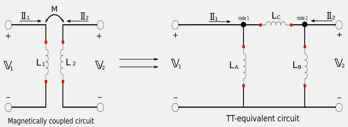
Once again, our goal is to obtain three expressions that will allow determine inductor values for the ΤΤ-equivalent circuit that are derived from the magnetically-coupled circuit.
Apply Kirchhoff's Current Law (KCL) to nodes 1 and 2 of TT-equivalent circuit:
For node 1 we get: $$ \frac{\mathbb{V}_1}{j\omega L_A} + \frac{\mathbb{V}_1 - \mathbb{V}_2}{j\omega L_C} = \mathbb{I}_1 $$ For node 2 we get: $$ \frac{\mathbb{V}_2 - \mathbb{V}_1}{j\omega L_C} + \frac{\mathbb{V}_2}{j\omega L_B} = \mathbb{I}_2 $$ If we were to put these two expressions in matrix form we would get: $$ \begin{pmatrix} \frac{1}{j\omega L_A}+\frac{1}{j\omega L_C}&-\frac{1}{j\omega L_C}\\ -\frac{1}{j\omega L_C}&\frac{1}{j\omega L_B}+\frac{1}{j\omega L_C}\\ \end{pmatrix} \begin{pmatrix} \mathbb{V}_1\\ \mathbb{V}_2\\ \end{pmatrix} = \begin{pmatrix} \mathbb{I}_1\\ \mathbb{I}_2\\ \end{pmatrix} \qquad ,(matrix \; eqn \; 3) $$
Take the inverse of matrix equation #1
Recall the matrix equation for the magnetically coupled circuit:
$$ \begin{pmatrix} j\omega L_1&j\omega M\\ j\omega M&j\omega L_2\\ \end{pmatrix} \begin{pmatrix} \mathbb{I}_1\\ \mathbb{I}_2\\ \end{pmatrix} = \begin{pmatrix} \mathbb{V}_1\\ \mathbb{V}_2\\ \end{pmatrix} \qquad ,(matrix \; eqn \; 1) $$ Using terms "A" "X" and "B", matrix equation #1 can be symbolized as: $$ A = \begin{pmatrix} j\omega L_1&j\omega M\\ j\omega M&j\omega L_2\\ \end{pmatrix} \;\;\; ,X = \begin{pmatrix} \mathbb{I}_1\\ \mathbb{I}_2\\ \end{pmatrix} \;\;\;, B = \begin{pmatrix} \mathbb{V}_1\\ \mathbb{V}_2\\ \end{pmatrix} \qquad , (Expression \;8) $$
Our goal is to make matrix equation #1 look something like matrix equation #3 so we can compare terms. We start by recognizing that for matrix equation #1: $$ AX = B $$ which means that: $$ X = A^{-1}B $$ This would allow us to compare matrix equations #1 and #3
We now want to take the inverse of The "A" term of equation #1. The inverse of this is defined as: $$ A^{-1} = \frac{1}{det(A)} adj(A) $$ Start by getting the determinant of "A": $$ det(A) = (j\omega L_1)(j\omega L_2)-(j\omega M)(j\omega M) $$ $$ det(A) = (j\omega)^2(L_1 L_2-M^2) $$ Additionally: $$ adj(A) = \begin{pmatrix} j\omega L_2&-j\omega M\\ -j\omega M&j\omega L_1\\ \end{pmatrix} $$ Therefore we now have: $$ A^{-1} = \frac{1}{(j\omega)^2(L_1 L_2-M^2)} \begin{pmatrix} j\omega L_2&-j\omega M\\ -j\omega M&j\omega L_1\\ \end{pmatrix} $$ $$ A^{-1} = \begin{pmatrix} \frac{L_2}{j\omega (L_1L_2-M^2)}&\frac{-M}{j\omega (L_1L_2-M^2)}\\ \frac{-M}{j\omega (L_1L_2-M^2)}&\frac{L_1}{j\omega (L_1L_2-M^2)}\\ \end{pmatrix} $$
We now have the following matrix equation for the ΤΤ-equivalent circuit: $$ \begin{pmatrix} \frac{L_2}{j\omega (L_1L_2-M^2)}&\frac{-M}{j\omega (L_1L_2-M^2)}\\ \frac{-M}{j\omega (L_1L_2-M^2)}&\frac{L_1}{j\omega (L_1L_2-M^2)}\\ \end{pmatrix} \begin{pmatrix} \mathbb{V}_1\\ \mathbb{V}_2\\ \end{pmatrix} = \begin{pmatrix} \mathbb{I}_1\\ \mathbb{I}_2\\ \end{pmatrix} \qquad ,(matrix \; eqn \; 4) $$
Compare terms for matrix equations #3 and #4:
When we compare terms for these two matrixes we get the following expressions:
Expressions for transforming a magnetically-coupled circuit to a ΤΤ-equivalent circuit:
$$ L_A = \frac{L_1L_2-M^2}{L_2-M} $$ $$ L_B = \frac{L_1L_2-M^2}{L_1-M} $$ $$ L_C = \frac{L_1L_2-M^2}{M} $$
Up next is an example problem:
Continue on to Linear transformers and T-equivalent circuit example problem...