An autotransformer has a single continuous winding (as opposed to two windings) with a connection point in between the primary and secondary (called a "tap"). The tap allows for an adjustable turns ratio. Adjusting the turns ratio allows for a step-up (n>1) or step down (n<1) configuration. Compared to a conventional transformer, the coils of an autotransformer are coupled conductively as well as magnetically (as opposed to only magnetic coupling). The disadvantage of this configuration is the lack of electrical isolation. An advantage however, is the ability to transfer larger apparent power values. Additionally, just like with an ideal transformer, there are no losses in an ideal autotransformer.
Step-down transformer
A step-down configuration looks like the following:
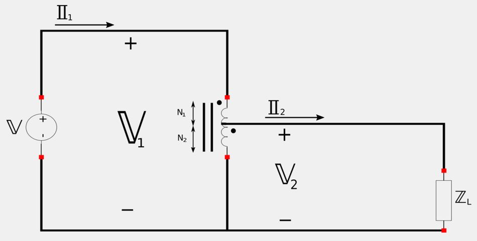
When equating the ratio of the secondary/primary voltages with the number of turns in the winding, the step-down configuration gives us the following: $$ \frac{\mathbb{V}_2}{\mathbb{V}_1} = \frac{N_2}{N_1+N_2} $$ For secondary and primary currents we have: $$ \frac{\mathbb{I}_2}{\mathbb{I}_1} = \frac{N_1+N_2}{N_2} $$
Step-up transformer
A step-up configuration looks like the following:
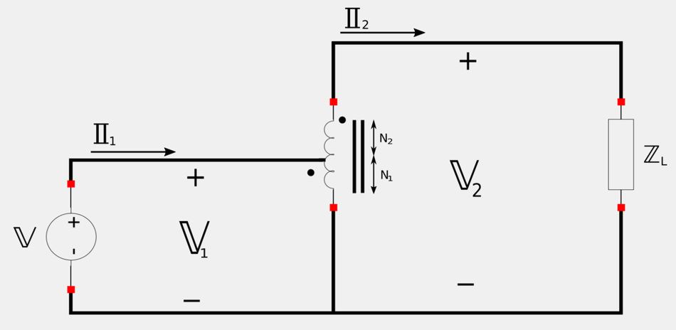
Primary and secondary voltage and currents for a step-up configuration can be expressed as: $$ \frac{\mathbb{V}_2}{\mathbb{V}_1} = \frac{N_1+N_2}{N_1} $$ $$ \frac{\mathbb{I}_2}{\mathbb{I}_1} = \frac{N_1}{N_1+N_2} $$
Power:
As was mentioned above, there is no power loss in an ideal autotransformer. When using RMS values for voltage and current, we have: $$ \mathbb{S}_1 = \mathbb{V}_1 \mathbb{I}_1^* = \mathbb{V}_2 \mathbb{I}_2^* = \mathbb{S}_2 $$
Next we will look at an example problem involving a step-up autotransformer.
Continue on to autotransformers (step-up example problem)...