When one particular loop of a circuit affects another loop by means of current conduction, we have what is called a "conductively-coupled circuit." However, when two loops with no physical connections between them are able to affect one another by means of a magnetic field generated by one of the loops, we have what is called a "magnetically-coupled circuit."
Self Inductance:
Consider a circuit having a single inductor with a coil of "N" number of turns as well as the indicated magnetic field:
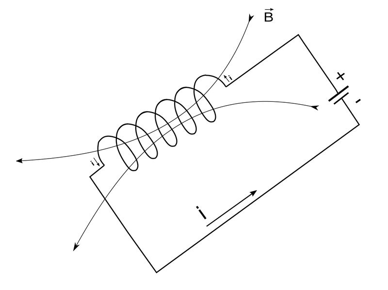
By Faraday's Law of Induction, the voltage across the coil is defined as: $$ v_L = N \frac{d \Phi_B}{dt} \qquad,(Eqn \; 1)$$ ...where: $$ \Phi_B = magnetic \; flux $$ While we won't address the physics associated with electromagnetism, know that the magnetic flux will change if the current changes and if this is an AC circuit, the current will obviously be time varying. This knowledge allows us to rewrite equation #1 as: $$ v_L = N \frac{d \Phi_B}{di} \frac{di}{dt} \qquad,(Eqn \; 2) $$ Since it is also known that the definition of inductance is: $$ L = N \frac{d \Phi_B}{di} $$ ...we can rewrite equation #2 as: $$ v_L = L \frac{di}{dt} \qquad,(Eqn \; 3) $$ You may recognize equation #3 as being the voltage-current relationship for an inductor.
Mutual Inductance:
Now consider what happens when we have two coils in close physical proximity to one another, each having a self-inductance value of L1 and L2:
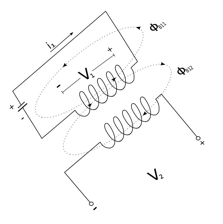
We will assume that coil 1 has "N1" number of turns and coil two has "N2" number of turns. Additionally we will assume that no current flows through the second conductor. Additionally, let: $$ \Phi_{B1} = total \;magnetic \; flux \; generated \; from \; coil \; 1 $$ $$ \Phi_{B1} = \Phi_{B11} + \Phi_{B12} $$ The magnetic flux labeled "B11" is the component of the total flux which passes solely through coil #1. The magnetic flux labeled "B12" is the component of the total flux which passes through both coil #1 and coil#2. The two coils are said to be coupled due to the fact that the total magnetic flux (B1) links both coils.
Induced Voltage in Coil #1:
By Faraday's Law we have: $$ V_1 = N_1 \frac{d \Phi_{B1}}{dt} $$ We see that all of the magnetic flux "B1" passes through coil #1 and this flux is caused by the current flowing through coil #1 (i1). $$ V_1 = N_1 \frac{d \Phi_{B1}}{di_1} \frac{di_1}{dt} $$ $$ V_1 = L_1 \frac{di_1}{dt} $$ ...where: $$ L_1 = self \; inductance \; of \; coil \; 1 $$
Induced Voltage in Coil #2:
Once again, by Faraday's Law we have: $$ V_2 = N_2 \frac{d \Phi_{B12}}{dt} $$ We see that only magnetic flux "B12" passes through coil #2. However, this flux is also caused by the current flowing in coil #1 (i1). $$ V_2 = N_2 \frac{d \Phi_{B12}}{di_1} \frac{di_1}{dt} $$
$$ V_2 = M_{21} \frac{di_1}{dt} \qquad, (Eqn\;4)$$ ...where: $$ M_{21} = N_2 \frac{d \Phi_{B12}}{di_1} $$ $$ \qquad = mutual \; inductance \; of \; coil \; 2 \; with \; respect $$ $$ \qquad \quad \;\; to \; coil \; 1 $$
Above, we see that the voltage induced in coil #2 is related to the current in coil #1.
Current flows through coil #2 but not coil #1
We now consider a situation that is opposite of the one above. Now a current (i2) is allowed to flow through coil #2 but not coil #1:
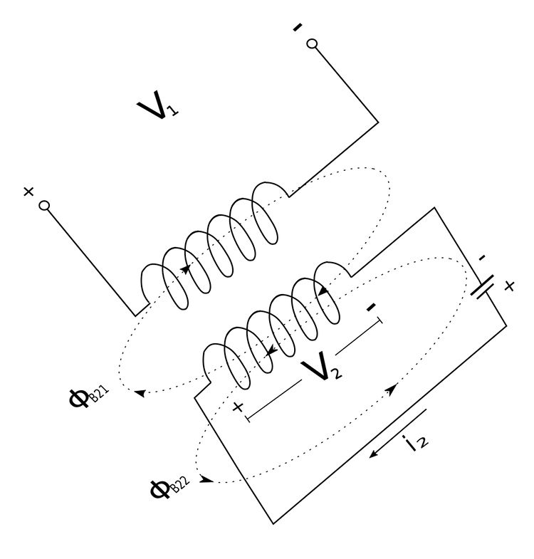
$$ \Phi_{B2} = total \;magnetic \; flux \; generated \; from \; coil \; 2 $$ $$ \Phi_{B2} = \Phi_{B21} + \Phi_{B22} $$ The magnetic flux labeled "B22" is the component of the total flux which passes solely through coil #2. The magnetic flux labeled "B21" is the component of the total flux which passes through both coil #1 and coil#2. Once again, by Faraday's Law we have the following expression for the voltage across coil #2: $$ V_2 = N_2 \frac{d\Phi_{B2}}{dt} $$ Since all of the magnetic flue ("B2") flows through coil #2 and is caused by the current i2, we have: $$ V_2 = N_2 \frac{d\Phi_{B2}}{di_2} \frac{di_2}{dt} $$ $$ V_2 = L_2 \frac{di_2}{dt} $$ $$ L_2 = self \; inductance \; of \; coil \; 2 $$ For the voltage across coil #1 we have: $$V_1 = N_1 \frac{d\Phi_{B21}}{dt}$$ Since only the magnetic flue ("B21") flows through coil #1 and is caused by the current i2, we have: $$ V_1 = N_1 \frac{d\Phi_{B21}}{di_2} \frac{di_2}{dt} $$
$$ V_1 = M_{12} \frac{di_2}{dt} \qquad,(Eqn\;5) $$ ...where: $$ M_{12} = N_1 \frac{d \Phi_{B21}}{di_2} $$ $$ \qquad = mutual \; inductance \; of \; coil \; 1 \; with \; respect $$ $$ \qquad \quad \;\; to \; coil \; 2 $$
While the following is not proven here, know that: $$ M_{12} = M_{21} = M $$ "M" is the mutual inductance between the two coils and is measured in units of Henrys. This means we now have the following expressions for the mutually induced voltage across the two coils: $$ V_1 = M \Big( \frac{di_2}{dt} \Big) $$ $$ V_2 = M \Big( \frac{di_1}{dt} \Big) $$ However, if you take a look at the section on Phasor Calculus you may realize that we can make the following substitution: $$ \frac{di}{dt} = j \omega \mathbb{I} $$ Therefore, the mutually induced voltages across the coils can also be expressed in the frequency domain as: $$ \mathbb{V}_1 = j \omega M \mathbb{I}_2 $$ $$ \mathbb{V}_2 = j \omega M \mathbb{I}_1 $$
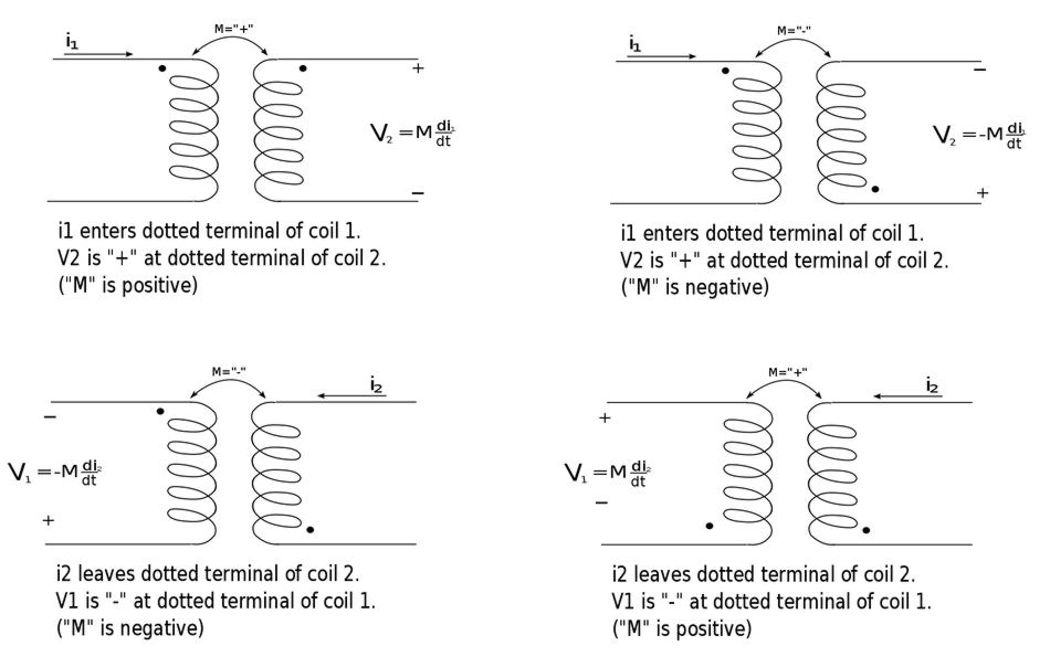
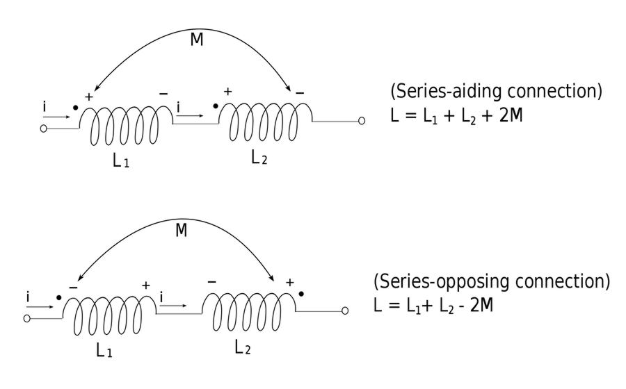
Determining polarity of mutually induced voltages (Dot-Convention):
In regards to the self-induced voltage (L di/dt) the polarity is determined by the reference direction of the current flow in relation to the passive sign convention. The polarity of the mutually induced voltage (M di\dt) is somewhat more difficult as it relies on Lenz's Law and the Right Hand Rule as well as the knowledge of how the coils are physically wound. Since it is impractical to annotate such information in an electrical schematic something called the "Dot Convention" is often used. In the dot convention, a dot is placed at one end of each magnetically coupled coil. The dot indicates the direction of magnetic flux if the current was to enter that particular terminal of the coil. The following statement explains this convention in relation to polarity
- IF a current ENTERS the dotted terminal in one coil...
- THEN the polarity of the mutually induced voltage is POSITIVE at the dotted terminal of the other coil.
Conversely:
- IF a current LEAVES the dotted terminal in one coil...
- THEN the polarity of the mutually induced voltage is NEGATIVE at the dotted terminal of the other coil.
The following schematics will helpfully illustrate the above statements:
click here for PDF version of above illustration
Steps for solving mutually coupled circuits:
- Determine the sign for the induced voltages.
- Determine the value of the induced voltages. $$ \mathbb{V}_2 = j\omega M \mathbb{I}_1 $$ $$ \mathbb{V}_1 = j\omega M \mathbb{I}_2 $$
- Analyze this circuit containing two dependent sources.
For purposes of our analysis here, the value of "M" and the location of the dots are taken as given.
Recap
For two coils in close proximity to one another, the mutually induced voltage across them is defined as: $$ V_1 = M \Big( \frac{di_2}{dt} \Big) , \;\;\; \mathbb{V}_1 = j \omega M \mathbb{I}_2 $$ $$ V_2 = M \Big( \frac{di_1}{dt} \Big) , \;\;\; \mathbb{V}_2 = j \omega M \mathbb{I}_1 $$
In the next page we will look at an example problem involving mutual inductance
Continue on to Mutual Inductance example problem #1...