Overview
A notable characteristic of ideal transformers is that of perfect coupling (k=1). Ideal transformers have a core of high magnetic permeability in which the magnetic flux links all of the turns of both coils. The two coils also share a single common core.
Properties of Ideal Transformers:
- Coils have large reactances (L1, L2, M -> infinity)
- Coupling coefficients equal unity (k=1)
- Primary and secondary coils have no losses
In terms of real world applications, iron-core transformers closely approximate ideal transformers. Such a transformer is symbolized schematically with two vertical lines in between the two coils.
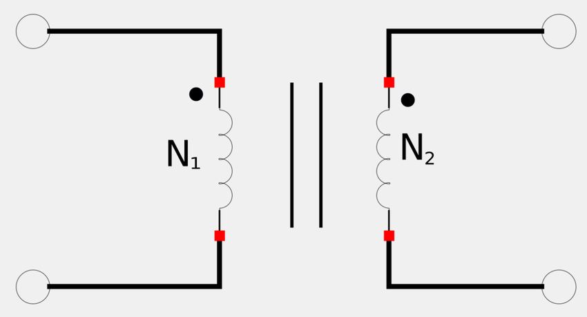
Turns Ratio
In the above figure, the primary winding has N1 number of turns and the secondary winding has N2 number of turns. Recalling Faraday's Law gives us the following two expressions for V1 and V2: $$ \mathbb{V}_1 = N_1 \frac{d \Phi_B}{dt} $$ $$ \mathbb{V}_2 = N_2 \frac{d \Phi_B}{dt} $$ If we wanted to express the ratio of secondary voltage over primary voltage we would get: $$ \frac{\mathbb{V}_2}{\mathbb{V}_1} = \frac{N_2}{N_1} = n$$ ...where: $$ \frac{N_2}{N_1} = n = "turns\;ratio" $$ "Turns ratio" is sometimes called the "transformer ratio". Due to the principle of conservation of power, the energy supplied by the primary must equal the energy absorbed by the secondary. Therefore: $$ \mathbb{V}_1 \mathbb{I}_1 = \mathbb{V}_2 \mathbb{I}_2 $$ $$ \frac{\mathbb{I}_1}{\mathbb{I}_2} = \frac{\mathbb{V}_2}{\mathbb{V}_1} = n $$
Turns ratio
$$ \frac{\mathbb{V}_2}{\mathbb{V}_1} = \frac{N_2}{N_1} = n $$ $$ \frac{\mathbb{I}_2}{\mathbb{I}_1} = \frac{N_1}{N_2} = \frac{1}{n} $$
Depending on the turns ratio, we can have three types of ideal transformers:
- n=1: "isolation transformer"
- n>1: "step-up transformer" (V2>V1)
- n<1: "step-down transformer" (V2<V1)
Commercially, transformers are often rated as V1/ V2. For example: $$ \frac{2400}{120}V $$ ...means 2400V on the primary side and 120V on the secondary. These are assumed to be RMS values
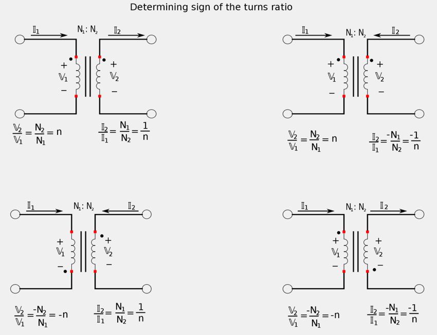
Sign of "n" depends of voltage polarity and current direction
$$ A)\; IF \; \mathbb{V}_1 \; and \; \mathbb{V}_2 \; are \; both \; negative \; OR \; both \; positive, $$ $$ \quad \; at \; the \; dotted \; terminals: $$ $$ \quad \; THEN \; use "+n" $$ $$ \quad \; ELSE \; use "-n" $$ $$ B) \; IF \; \mathbb{I}_1 \; and \; \mathbb{I}_2 \; both \; enter \; OR \; both \; leave \; the $$ $$ \quad \; dotted \; terminals: $$ $$ \quad \; THEN \; use \; "-n" $$ $$ \quad \; ELSE \; use \; "+n" $$
The following images help explain these rules:
click here for PDF version of above illustration
Power in ideal transformers
Recall the following expressions for the turns ratio: $$ \frac{\mathbb{V}_2}{\mathbb{V}_1} = \frac{N_2}{N_1} = n $$ $$ \frac{\mathbb{I}_2}{\mathbb{I}_1} = \frac{N_1}{N_2} = \frac{1}{n} $$ If we want to express V1 in terms of V2 and I1 in terms of I2 we have: $$ \mathbb{V}_1 = \frac{\mathbb{V}_2}{n} $$ $$ \mathbb{I}_1 = n\mathbb{I}_2 $$ Next, consider that the complex power of the primary side can be expressed as: $$ \mathbb{S}_1 = \mathbb{V}_1 \mathbb{I}_1^* $$ ...where the phasor voltages and currents are understood to be RMS values. Next, we use the substitutions derived from the turns ratio above and get: $$ \mathbb{S}_1 = \Big( \frac{\mathbb{V}_2}{n} \Big) (n\mathbb{I}_2)^* $$ $$ \mathbb{S}_1 = \mathbb{V}_2 \mathbb{I}_2^* = \mathbb{S}_2 $$ We now see that the ideal transformer absorbs no power (is lossless). The power supplied to the primary equals the power delivered to the secondary.
Reflected impedance in ideal transformers
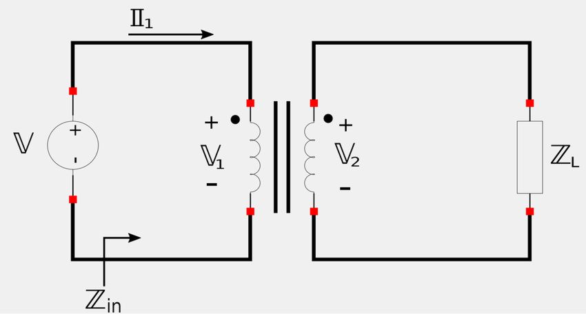
In the above figure, we see that input impedance can be defined as: $$ \mathbb{Z}_{in} = \frac{\mathbb{V}_1}{\mathbb{I}_1} $$ However, if we substitute the aboved-derived expressions for the turns ratio, we can rewrite this expression as: $$ \mathbb{Z}_{in} = \frac{\mathbb{V}_2}{n} \Big( \frac{1}{n\mathbb{I}_2} \Big) $$ $$ \quad \; = \frac{\mathbb{V}_2}{n^2 \mathbb{I}_2} $$ But, notice that: $$ \qquad \qquad \frac{\mathbb{V}_2}{\mathbb{I}_2} = \mathbb{Z}_L $$ Therefore, input impedance for an ideal transformer is:
$$ \mathbb{Z}_{in} = \frac{\mathbb{Z}_L}{n^2} = \mathbb{Z}_R$$
This is also referred to as "reflected impedance" because the load impedance is reflected to the primary side.
Impedance matching
One interesting thing to note about the expression for input impedance is that an ideal transformer can "transform" a given impedance into another impedance. This is important in "impedance matching" and allowing for maximum power transfer where the source impedance needs to match the reflected load impedance. More detailed information on impedance matching will be covered in another section.
In the next section we will look a how one can construct equivalent circuits for an ideal transformer.
Continue on to Ideal transformer equivalent circuits...