For the following circuit:
All values are RMS
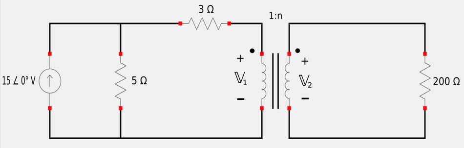
- A) Determine "n" for maximum power supplied to 200 ohm load.
- B) Determine the power in the 200 ohm load if n=10
Simplfy analysis by replacing current source with Thevenin equivalent
$$ \mathbb{V}_{th} = 15 \angle 0^{\circ}(5) = 75 \angle 0^{\circ} \; V $$
Primary side replaced with Thevenin equivalent:
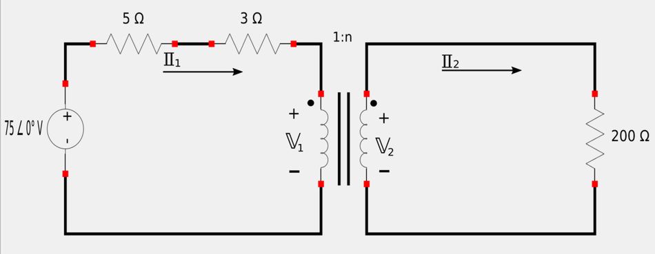
Using the rules for determining the sign of the turns ratio, we have: $$ "+n" \; for \; voltage \; and \; current $$
A) Determine "n" for maximum power supplied to 200 ohm load.
For maximum power transfer, the source impedance needs to equal the reflected impedance from the load. $$ \mathbb{Z}_s = \mathbb{Z}_R $$ Recalling that reflected impedance is defined as: $$ \mathbb{Z}_R = \frac{\mathbb{Z}_L}{n^2} $$ ...we have: $$ 8 = \frac{200}{n^2} $$ $$ n = \sqrt{\frac{200}{8}} $$
$$ n = 5 = \; "turns \; ratio" $$
A) Alternative method (equivalent circuit: reflect the secondary side to the primary)
Recall the rules for equivalent circuits of ideal transformers. Realizing that if we want to reflect the secondary to the primary, the secondary impedance (load impedance in our case) will be: $$ \mathbb{Z}_L = \frac{200}{n^2} $$ Our equivalent circuit will look like the following:
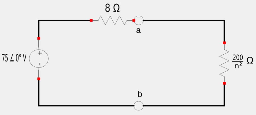
For maximum power transfer, the source impedance needs to equal the load impedance: $$ \mathbb{Z}_s = \mathbb{Z}_L $$ $$ 8 = \frac{200}{n^2} $$ Once again we get: $$ n = 5 = \; "turns \; ratio" $$
B) Determine power in 200 ohm load if n=10
Recall our Thevenin equivalent of the original circuit:
We need to determine the value of I2.
Applying Kirchhoff's Voltage Law (KVL) to the primary side:
$$ 8\mathbb{I}_1+\mathbb{V}_1 = 75 \qquad, (Eqn\;1)$$ However, from the turns ratio, we have: $$ \qquad \frac{\mathbb{I}_2}{\mathbb{I}_1} = \frac{1}{n} $$ $$ \qquad \mathbb{I}_1 = n\mathbb{I}_2 = 10\mathbb{I}_2 $$ Equation #1 now becomes: $$ 80\mathbb{I}_2+\mathbb{V}_1 = 75 \qquad(Eqn\;A) $$
Apply KVL to the secondary side:
$$ 200\mathbb{I}_2 - \mathbb{V}_2 = 0 \qquad,(Eqn\;2) $$ However, from the turns ratio, we have: $$ \qquad \frac{\mathbb{V}_2}{\mathbb{V}_1} = n $$ $$ \qquad \mathbb{V}_2 = n\mathbb{V}_1 = 10\mathbb{V}_1 $$ Equation #2 now becomes: $$ 200\mathbb{I}_2 - 10\mathbb{V}_1 = 0 \qquad(Eqn\;B) $$ If you solve equations A and B (by whatever means you choose), you will get: $$ \mathbb{I}_2 = 0.75\;A \quad, \mathbb{V}_1=15\;V $$ Recalling the expressions for complex power, we have the following expression for the complex power in the 200 ohm resistor (which is also the real power since the load is purely resistive: $$ \mathbb{S}_{200\Omega} = (I_{rms})^2 \mathbb{Z} = P_{200\Omega} $$ $$ \qquad \; = (0.75)^2(200) $$
$$ P_{200\Omega} = 112.5 \; W $$
B) Determine power in 200 ohm load if n=10 (using equivalent circuit):
Alternatively, we can find the power in the 200 ohm resistive load using our above-derived equivalent circuit (also shown below):
With n=10, the equivalent load is: $$ \mathbb{Z}_L = \frac{200}{10^2} = 2 \; \Omega $$ The current through the load can be defined as: $$ \mathbb{I} = \frac{75}{8+2} = 7.5 \; A $$ Finally, the power through the load is: $$ \mathbb{S}_{200\Omega} = (I_{rms})^2 \mathbb{Z} = P_{200\Omega} $$ $$ \qquad \; = (7.5)^2(2) $$ We end up getting the same answer as above:
$$ P_{200\Omega} = 112.5\;W $$