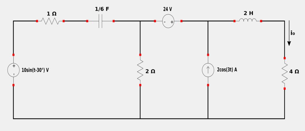
For the following circuit, determine i0 using the Superposition Theorem:
Recall the steps taken to analyze a circuit using the Superposition Theorem:
- "Turn off" all independent sources except one source. Determine the output voltage/current due to the remaining source.
- Repeat step #1 for each remaining independent source.
- Find the total contribution by adding all of the individual contributions from each independent source.
Step 1: Let i1 = io due to the AC voltage source acting alone:
For the AC voltage source, note that the angular frequency (omega) is equal to 1. Start by converting everything to the frequency domain (starting with the voltage source). When refering to the Phasor Notation tutorial, you may recall that when converting from sinusoidal to phasor notation, we first ensure that the sinusoid is expressed in cosine form with a positive amplitude. Thus: $$ 10\sin(t-30^{\circ}) = 10\cos(t-30^{\circ}-90^{\circ}) $$ $$ \qquad \qquad \qquad \; \; = 10\cos(t-120^{\circ}) $$ $$ 10\sin(t-30^{\circ}) = 10 \angle (-120^{\circ}) \; V$$ Obtain the impedance value for the capacitor: $$ \mathbb{Z}_C = \frac{-j}{\omega C} = \frac{-j}{(1)\frac{1}{6}} = -j6 \; \Omega$$ Obtain the impedance value for the inductor: $$ \mathbb{Z}_L = j\omega L = j(1)(2) = j2 \; \Omega $$ We now proceed to "turn off" the 24 VDC voltage source and AC current source (Leaving only the AC voltage source). The circuit is now redrawn below (Complete with the above-calculated impedance values and symbolic mesh currents IIs and IIt):
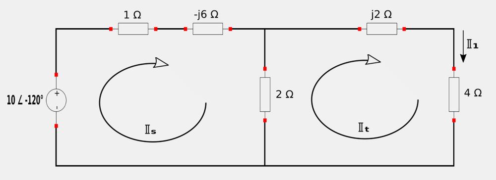
Our goal is to find phasor current II1 (which is the component of io (in phasor form) due only to the AC voltage source). Applying Kirchhoff's Voltage Law (KVL) to mesh IIs: $$ \mathbb{I}_s - j6\mathbb{I}_s + +2(\mathbb{I}_s - \mathbb{I}_t) = 10 \angle (-120^{\circ}) $$ $$ \mathbb{I}_s(3-j6) - 2\mathbb{I}_t = 10 \angle (-120^{\circ}) $$ Converting the above expression to polar form:
$$ 6.708\mathbb{I}_s \angle (-63.43^{\circ}) - 2\mathbb{I}_t \angle 0^{\circ} = 10 \angle (-120^{\circ}) \;\;\;,(A)$$
Applying KVL to mesh IIt: $$ 2(\mathbb{I}_t - \mathbb{I}_s) + j2\mathbb{I}_t + 4\mathbb{I}_t = 0 $$ $$ -2\mathbb{I}_s + \mathbb{I}_t(6+j2) = 0 $$ Multiplying the above expression by -1: $$ 2\mathbb{I}_s - \mathbb{I}_t(6+j2) = 0 $$ ...and then converting it to polar form:
$$ 2\mathbb{I}_s \angle 0^{\circ} - 6.324\mathbb{I}_t \angle 18.43^{\circ} = 0 \;\;\;,(B)$$
We now use Cramer's Rule to solve for equations A and B. Start by creating an augmented matrix of coefficients from our system of equations:
$$ \begin{pmatrix} 6.708 \angle (-63.43^{\circ})&-2 \angle 0^{\circ}&10 \angle (-120^{\circ})\\ 2\angle 0^{\circ}&-6.324 \angle 18.43^{\circ}&0\\ \end{pmatrix} $$ Find the determinant of the non-augmented matrix of coefficients: $$ D = \begin{vmatrix} 6.708 \angle (-63.43^{\circ})&-2 \angle 0^{\circ}\\ 2\angle 0^{\circ}&-6.324 \angle 18.43^{\circ}\\ \end{vmatrix} $$
$$ D = 39.69 \angle 130.9^{\circ} $$
Create a matrix that consists of the non-augmented matrix of coefficients with its 1st column replaced by the 3rd column of the augmented matrix of coefficients and find its determinant: $$ D_{\mathbb{I}_t} = \begin{vmatrix} 6.708 \angle (-63.43^{\circ})&10 \angle (-120^{\circ})\\ 2\angle 0^{\circ}&0\\ \end{vmatrix} = 20 \angle 60^{\circ} $$
From the above circuit, we know that: $$ \mathbb{I}_t = \mathbb{I}_1$$ ...and by Cramer's Rule: $$ \mathbb{I}_1 = \frac{D_{\mathbb{I}_t}}{D} = \frac{20 \angle 60^{\circ}}{39.69 \angle 130.9^{\circ}} $$ $$ \mathbb{I}_1 = 0.5039 \angle (-70.9^{\circ}) = 0.5039e^{j(-70.9^{\circ})} $$ Note that the three sources in our original circuit are operating at different frequencies. This means that we need to convert each of the individual currents to the time domain prior to adding them. So go ahead and do this for the above phasor current by multiplying by e^jwt (omega=1) and taking the real part of the result:
$$ i_1 = R_e \{ 0.5039e^{j(-70.9^{\circ})}e^{j(1)t} \} $$ $$ i_1 = R_e \{ 0.5039e^{j(t-70.9^{\circ})} \} $$ Using Euhler's Identity gives us: $$ i_1 = R_e \{ 0.5039\cos(t-70.9^{\circ}) +j0.5039\sin(t-70.9^{\circ}) \} $$ By evaluating the above expression we get:
$$ i_1 = 0.5039\cos(t-70.9^{\circ}) $$
Step 2: Let i2 = io due to the AC current source acting alone:
For the AC current source we note that: $$ \omega = 3 $$ Once again we convert to the frequency domain beginning with the current source : $$ 2\cos 3t = 2 \angle 0^{\circ} \; A $$ Obtain the impedance value for the capacitor: $$ \mathbb{Z}_C = \frac{-j}{\omega C} = \frac{-j}{(3)\frac{1}{6}} = -j2 \; \Omega$$ Obtain the impedance value for the inductor: $$ \mathbb{Z}_L = j\omega L = j(3)(2) = j6 \; \Omega $$
We now redraw the original circuit at the top of the page but with the AC voltage source and 24 VDC source "turned off" and the circuit elements converted to the frequency domain:
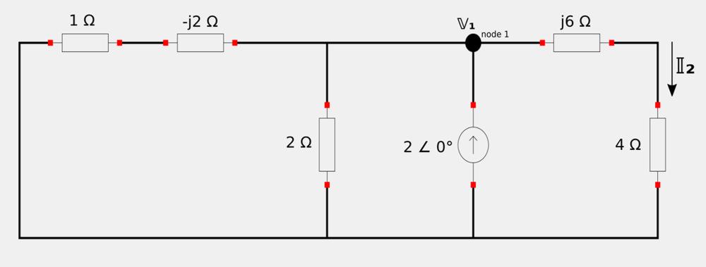
Our goal is to obtain phasor current II2. Begin by Applying Kirchhoff's Current Law (KCL) at node 1: $$ \frac{\mathbb{V}_1}{2} + \frac{\mathbb{V}_1}{1-j2} + \frac{\mathbb{V}_1}{4+j6} = 2 \angle 0^{\circ} $$ Multiply the complex terms by their complex conjugates: $$ \frac{\mathbb{V}_1}{2} + \frac{\mathbb{V}_1}{1-j2} \Big( \frac{1+j2}{1+j2} \Big) + \frac{\mathbb{V}_1}{4+j6} \Big( \frac{4-j6}{4-j6} \Big) = 2 \angle 0^{\circ} $$ $$ \frac{\mathbb{V}_1}{2} + \frac{\mathbb{V}_1 (1+j2)}{5} + \frac{\mathbb{V}_1 (4-j6)}{52} = 2 \angle 0^{\circ} $$ $$ \mathbb{V}_1 \Big( \frac{1}{2} + \frac{1}{5} + j\frac{2}{5} + \frac{1}{13} - j\frac{3}{26} \Big) = 2 \angle 0^{\circ} $$ $$ \mathbb{V}_1(0.7769 + j0.2846) = 2 \angle 0^{\circ} $$ $$ 0.8274\mathbb{V}_1 \angle 20.12^{\circ} = 2 \angle 0^{\circ} $$ $$ \mathbb{V}_1 = 2.417 \angle (-20.12^{\circ}) $$
Now that we have determined V1, we proceed to use Ohm's Law to deterine II2: $$ \mathbb{I}_2 = \frac{\mathbb{V}_1}{4+j6} $$ $$ \mathbb{I}_2 = \frac{2.417 \angle (-20.12^{\circ}}{7.211 \angle 56.31^{\circ}} $$ $$ \mathbb{I}_2 = 0.3352 \angle (-76.43^{\circ}) = 0.3352e^{j(-76.43^{\circ})} $$
Once again remember that we need to transform the above expression to the time domain so we can add it later. To do so, multiply by e^jwt (omega = 3) and take the real part of the result: $$ i_2 = R_e \{ 0.3352e^{j(-76.43^{\circ})} e^{j3t} \} $$ $$ i_2 = R_e \{ 0.3352e^{j(3t-76.43^{\circ})} \} $$ Apply Euhler's Identity to the above expression and get: $$ i_2 = R_e \{ 0.3352\cos(3t-76.43^{\circ}) + j0.3352\sin(3t-76.43^{\circ}) \} $$ And then extracting only the real part gives us:
$$ i_2 = 0.3352\cos(3t-76.43^{\circ}) $$
Step 3: Let i3 = io due to the 24 VDC source acting alone:
When removing (or "turning off") the two AC voltage and current sources, we realize that the remaining 24 V source is not sinusoidal (it is constant). You may also recall that under DC (steady-state) conditions, a capacitor acts as an open circuit and an inductor acts as a short circuit. With all of this in mind, we redraw the original circuit and get the following:
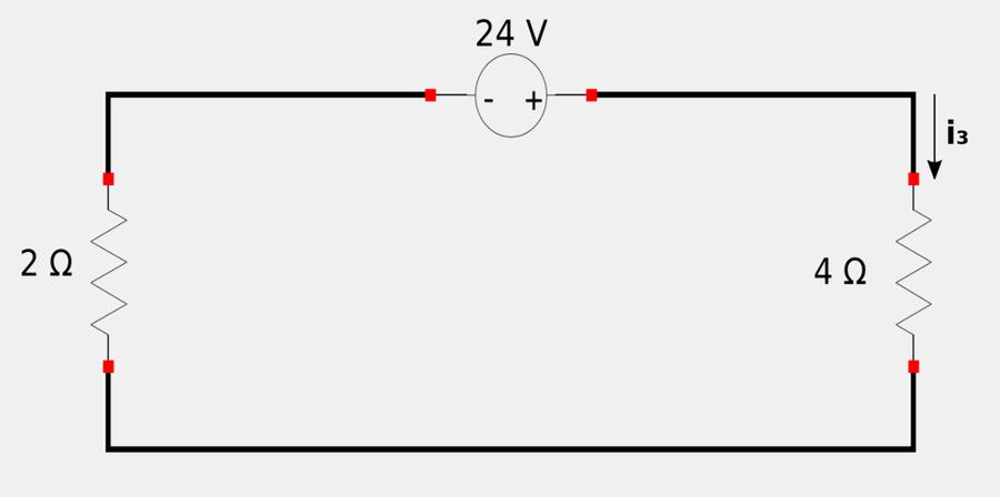
Determining i3 is a simple matter of implementing Ohm's Law and the rule for resistor's in series: $$ i_3 = \frac{24}{4+2} $$
$$ i_3 = 4 \; A $$ Note that i3 is already in the time-domain.
Find the total contribution by adding all of the individual contributions from each independent source:
$$ i_o = i_1 + i_2 + i_3 $$
Final Answer:
$$ i_o = 4 + 0.504\cos(t-70.9^{\circ}) + 0.335\cos(3t-76.4^{\circ}) \; A $$