Driving the Pulse Train

With our PIC microcontroller properly configured for analog to digital conversion, we can now go ahead and set up the "Enhanced Capture/Compare/PWM" (ECCP) module. Specifically, we will be configuring it to act in "full-bridge" output mode. This will allow us to control the motor in forward and reverse directions. The first step will involve configuring the Timer2 (TMR2) module which is how we will effectively control the frequency of our PWM output to the motor. Let's take a look at how the timing of our PWM pulses is controlled by TMR2.
Timer2:
The TMR2 module is driven by the instruction clock of the MCU. As was mentioned earlier, the instruction clock speed is the speed of the processor clock divided by four. We can slow down TMR2's rate of incrementation by using a prescaler ratio of 1:4 or 1:16. An important concept to keep in mind is that TMR2 works in conjunction with another register named "PR2". Essentially, TMR2 will increment until it reaches the value held in PR2 and then it will roll over and continue to increment/reset in this manner. Therefore, by giving an apppropriate prescale value to TMR2 as well as loading an appropriate value in the PR2 register, we can effectively create a "period" of a specific length during which time TMR2 is incrementing from zero to a predetermined value. This "period" will determine the frequency of our PWM output. Let's go ahead and first set up the "T2CON" register that configures Timer2:
| T2CON Register | |||||||
|---|---|---|---|---|---|---|---|
| 7 | 6 | 5 | 4 | 3 | 2 | 1 | 0 |
| Not Used | TOUTPS3 | TOUTPS2 | TOUTPS1 | TOUTPS0 | TMR2ON | T2CKPS1 | T2CKPS0 |
We will turn on the Timer2 module by setting bit #2 of the T2CON register as well as give it a prescale value of 1:4 (see data sheet for prescaler options) by loading the binary value "01" into bits number 0 and 1:
movlw b'00000101'
banksel T2CON
movwf T2CON
Our PIC will be running at 4Mhz, which gives an instruction cycle speed of 1Mhz (1 instruction every microsecond). With a prescaler of 1:4, TMR2 will be incrementing once every 4 microseconds from zero until whatever value we place in the PR2 register. This will be our period or frequency. As I mentioned a few pages ago, the proper frequency will vary from motor to motor and some trial and error may be necessary, With my particular motor, a frequency of about 1Khz worked well and produced little audible whine or ringing sound. So with that in mind we can now load a value into PR2 to give us roughly 1Khz (1000 Hz). Due to the limited options for the TMR2 prescale value, an exact period isn't always possible (depending on the number you are shooting for), but close is often good enough. Excessively low or high frequencies should be avoided however. In particular, extremely high frequencies may exceed the switching speed of your MOSFETS as well as consume excessive amounts of power. By loading the number 255, (maximum 8-bit number PIC registers can hold), I achieved a period of 1.02 milliseconds or about 980 Hz.
(4*10^-6) * 255 = (1.02*10^-3) = 980Hz
This was done as follows:
movlw .255
banksel PR2
movwf PR2
Since the PWM module in the PIC16F1937 can be configured to run off of the Timer 2, 4 or 6 modules, we need to tell it to use the Timer2 module we have just configured. Setting all but the first two bits of the CCPTMRS0 register does just that. (See page 185 of datasheet)
movlw b'11111100'
banksel CCPTMRS0
movwf CCPTMRS0
CCP1CON Register:
Probably the most complicated register is CCP1CON. Manipulating this register is how we determine the direction of the motor by setting one pin as a modulated output and the other three as high or low (on or off). In the "Full-Bridge Forward" mode which we will be utilizing, the P1D output (pin #30) is modulated, P1A/P1C are "active-low" and P1B/P1D are "active-high". The diagram below may help visualize things a bit:
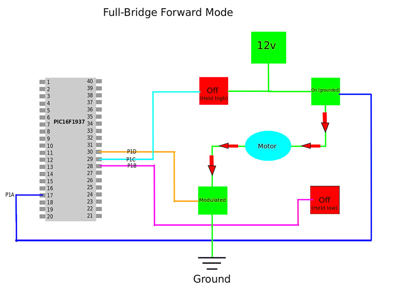
When using the terms "on/off" or "high/low" keep in mind exactly what this means regarding a P-Channel vs. N-Channel MOSFET and how the resistors connected to the MOSFET gates are holding each type of device in a default state of "OFF". Pulling the P-Channel MOSFETS "low" turns them on and pulling the N-Channel MOSFETS high turns them on. The inverse of this turns each type off. For example, P1C is configured as "active-low". When it is "active" it sends a binary "0" signal to the gate of the upper left P-Channel MOSFET which grounds the gate pin and switches the device "ON." In "Full-Bridge-Forward" P1C is "inactive" so the upper left P-Channel device remains "OFF". This is not something that is incredibly intuitive when explained with words so take a look at the CCP1CON register below and refer to pg 184 of the PIC16F1937 datasheet to help clear things up. Don't be surprised if you have to get this wrong several times until you stumble across the correct configuration. When you do get it working, take a good hard look at the bit values in the CCP1CON register and trace the path from each pin to the MOSFET until you make sense of it.
| CCP1CON Register | |||||||
|---|---|---|---|---|---|---|---|
| 7 | 6 | 5 | 4 | 3 | 2 | 1 | 0 |
| P1M1 | P1M0 | DC1B1 | DC1B0 | CCP1M3 | CCP1M2 | CCP1M1 | CCP1M0 |
Once again, I won't explain every possible way to configure this register, only what is relevant to our purposes. We will start by configuring the register in Full-Bridge-Forward mode as a default starting point. (This will be modified later in the program based on our potentiometer input). Doing this requires bits 6 and 7 to have the binary values 0 and 1 respectively. Bits 5 and 6 won't be utilized for this exercise but they basically serve as a hack to get more resolution out of the duty cycle. (We won't need this resolution so leave them cleared.) We have now specified P1D as a modulated output, but loading bits 0-3 with the binary value "1110" allows us to configure PID/P1C as active low and P1B/P1D as active-high. This setting jives with the configuration of our h-bridge with its high-side P-Channel MOSFETS and low-side N_Channel MOSFETS. With all of this in mind, we will now load the CCP1CON register with a single binary value to accomplish all of the above:
movlw b'01001110'
banksel CCP1CON
movwf CCP1CON
Dead-Band Delay:
As a final consideration, we will enter some code that will induce a certain amount of "Dead-Band Delay." Dead Band Delay is designed to prevent something called "shoot-through current". Shoot-through current occurs if an upper and lower MOSFET are both switched on at the same time. If this were to occur, large amounts of current would travel through both switches. Essentially, you would be shorting your power supply and killing the switches. (Not good). Since MOSFETS generally take longer to turn off than they do to turn on, it's something that needs to be taken into consideration and all MOSFET data sheets will list the turn on/off times. Dead Band delay ensures a small amount of lag time during transitions between active and inactive states of the microcontroller output pins. We can control the amount of dead-band delay through the PWM1CON register.
| PWM1CON Register | |||||||
|---|---|---|---|---|---|---|---|
| 7 | 6 | 5 | 4 | 3 | 2 | 1 | 0 |
| P1RSEN | P1DC6 | P1DC5 | P1DC4 | P1DC3 | P1DC2 | P1DC1 | P1DC0 |
Bit #7 can be ignored and left set to 0. The value you enter into bits 0-6 represents the number of instruction cycles that will be used for the delay period. To be on the safe side I will use a maximum delay by loading the binary value "1111111" (decimal number 127) into PWM1CON. Since our instruction clock period is one microsecond, we will obtain a dead-band delay of 127 microseconds. When consulting the datasheet for our Fairchild Semiconductor MOSFETS, the delay rise/fall times are all in the nanosecond range. Therefore, 127 microseconds is a generous cushion, yet still quick enough that it will not cause any detrimental effects on the operation of the h-bridge. This is something that will only occur when we change the direction of the motor from reverse to forward or vice-versa and the state of different pins change from inactive to active (or vice-versa). The code is as follows:
movlw b'01111111'
banksel PWM1CON
movwf PWM1CON
So upon completing the configuration of the ECCP module, we have also sucessfully configured the main registers we need to drive our h-bridge. This is a lot to digest at first and generally an unfamiliar concept if your prior experience with programming revolves around higher level languages that abstract away the intricate details found under the hood of every computer chip. Personally I find it quite interesting to realize that our incredibly complex digital world is far from magic and revolves around two basic physical electrical states: 1) The prescence of voltage at a particular location above a certain threshold level or 2) the lack thereof. The simple concept or 1/0, yes/no, true/false is the underlying foundation of our current digital society. While you would be hard pressed to find a legitimate reason to write long, complex programs in assembly language today (special cases do exist), there is a feeling of empowerment that comes from the basic understanding of how it all works. While most embedded programming and software/hardware interfacing is done in the C language (which allows for quite extensive low-level control itself), the knowledge of assembly is often crucial to debugging software written for these use cases. So with that being said, we will now proceed to write the main part of the program that will bring everything together.