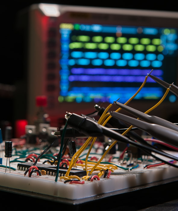
Visual Aids
The following oscilloscope and voltmeter images may help you to understand how our analog input is converted to a modulated pulse width and how the switching of the h-bridge MOSFETS are controlled. We will start from an input voltage of 0v and increase to the maximum input voltage (4.81v on my circuit.) For each voltage reading we will see what signals the oscilloscope captured on the P1A-P1D pins of the microcontroller. Keep in mind that pins P1A/P1C are configured as "active-low" and pins P1B/P1D are configured as "acive-high" due to the setting of the first two bits of the CCP1CON register being "10".
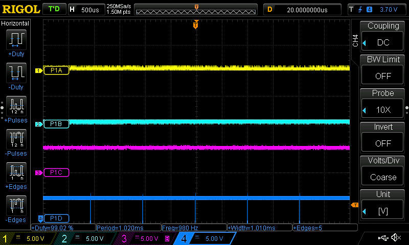
Zero volts (0v):
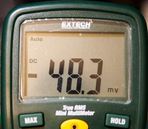
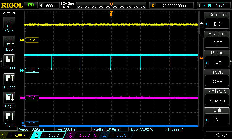
At an analog input of zero volts:
| CCP1CON configuration | Full-Bridge-Reverse-Mode |
| P1A | Inactive (held high) Upper right P-Channel MOSFET is OFF. |
| P1B | Modulated. (Duty cycle = 99%) Maximum reverse speed |
| P1C | Active (held low) Upper left P-Channel MOSFET is ON |
| P1D | Inactive (held low) Lower left N-Channel MOSFET is OFF |
1.153 Volts:
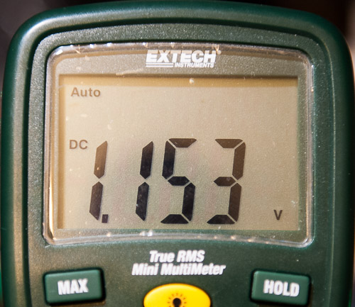
At an analog input of 1.153 volts:
| CCP1CON configuration | Full-Bridge-Reverse-Mode |
| P1A | Inactive (held high) Upper right P-Channel MOSFET is OFF. |
| P1B | Modulated. (Duty cycle = 50%) Half-speed in reverse direction |
| P1C | Active (held low) Upper left P-Channel MOSFET is ON |
| P1D | Inactive (held low) Lower left N-Channel MOSFET is OFF |
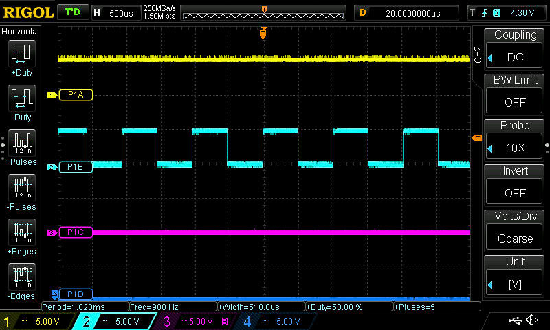
2.32 Volts:
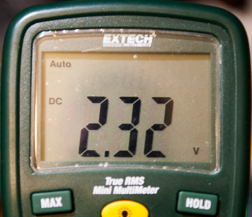
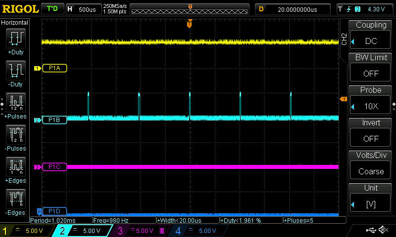
At an analog input of 2.32 volts:
| CCP1CON configuration | Full-Bridge-Reverse-Mode |
| P1A | Inactive (held high) Upper right P-Channel MOSFET is OFF. |
| P1B | Modulated. (Duty cycle = 1.96%) Close to slowest speed in the reverse direction. |
| P1C | Active (held low) Upper left P-Channel MOSFET is ON |
| P1D | Inactive (held low) Lower left N-Channel MOSFET is OFF |
2.42 Volts:
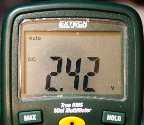
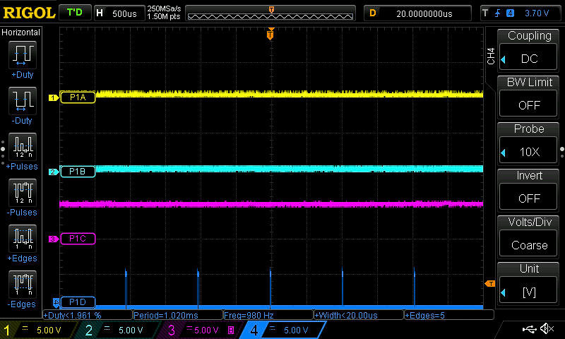
At an analog input of 2.42 volts:
| CCP1CON configuration | Full-Bridge-Forward-Mode |
| P1A | Active (held low) Upper right P-Channel MOSFET is ON. |
| P1B | Inactive (held low) Lower right N-Channel MOSFET is OFF. |
| P1C | Inactive (held high) Upper right P-Channel MOSFET is OFF |
| P1D | Modulated (Duty cycle = 1.96%) Close to slowest speed in the forward direction. |
3.61 Volts:
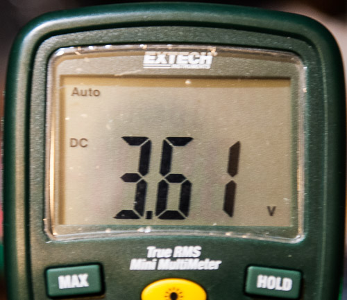
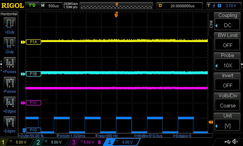
At an analog input of 3.61 volts:
| CCP1CON configuration | Full-Bridge-Forward-Mode |
| P1A | Active (held low) Upper right P-Channel MOSFET is ON. |
| P1B | Inactive (held low) Lower right N-Channel MOSFET is OFF. |
| P1C | Inactive (held high) Upper right P-Channel MOSFET is OFF |
| P1D | Modulated (Duty cycle = 50%) Half-speed in the forward direction. |
4.81 Volts:
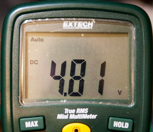
At an analog input of 3.61 volts:
| CCP1CON configuration | Full-Bridge-Forward-Mode |
| P1A | Active (held low) Upper right P-Channel MOSFET is ON. |
| P1B | Inactive (held low) Lower right N-Channel MOSFET is OFF. |
| P1C | Inactive (held high) Upper right P-Channel MOSFET is OFF |
| P1D | Modulated (Duty cycle = 99%) Full-speed in the forward direction. |
Video
The video below shows the potentiometer being turned through its full range of voltage values and the corresponding output captured by the oscilloscope. It may be hard to see the direction of the motor changing in the video (a piece of blue tape was attached to help) but the sound should clearly indicate a change in speed. Initially you can easily see the duty cycle changing on the PIB pin. Part way through the video I changed the triggering on the oscilloscope so that it was easier to see the duty cycle changing on the P1D pin. The video may not show it clearly, but there is some noise in the signals which means I need to do a better job of isolating the motor circuit from the logic circuit, but it's a decent starting point to work from.
Conclusion
Hopefully all of this has helped clarify some of the more confusing aspects of controlling a DC motor with a microcontroller. Like anything, trial and error as well as a lot of experimenting on your own is really the only way to fully grasp the process from beginning to end. The next page contains some links of possible interest, as well as the datasheets for the various devices we have used in this project.