
Now that we have a decent enough idea of what an h-bridge is and the general theory of how it operates, let's get started putting it all together:
Connect switch and LED to motor voltage supply (optional).
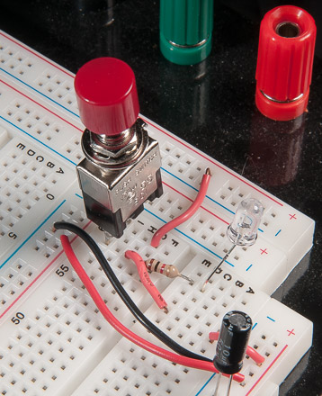
A switch wired to an LED can save you a few headaches. When troubleshooting problems it's much easier to quickly rule out whether or not your circuit has power with an indicator light.
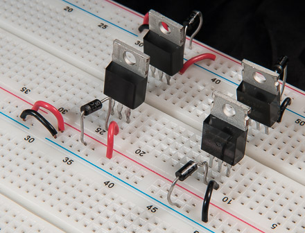
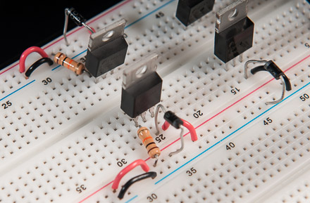
(Step #1) Place the four MOSFETS in the bread board:
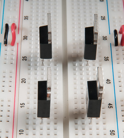
The top two MOSFETS are the P-Channel type. The bottom two MOSFETS are the N-Channel type.
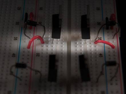
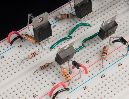
(Step #2) Connect protective diodes:
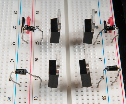
When a running DC motor is suddenly shut off, the resulting inductive voltage spike can damage the MOSFETS. These Schottky diodes (often referred to as "flyback diodes" in this application) short the induced voltage to the opposite terminal of the motor. For the two "high side" P-Channel MOSFETS it shorts this voltage to the positive rail of the motor voltage supply (which is the same as shorting it to the source pin.) The 2 "low side" N-Channel MOSFETS have the diode connected to the ground rail of the motor power supply which also effectively shorts the inductive kickback voltge to the source pin.
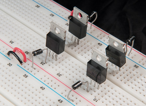
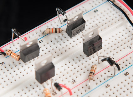
(Step #3) Connect source pins of P-Channel MOSFETS to the positive rail:
In order for our DC motor to run at all, the "high-side" P-Channel MOSFETS need to have a voltage source to switch on/off. Therefore, connect their source pins to the voltage supply of the motor circuit. (12 volts in my case.)
(Step #4) Connect source pins of N-Channel MOSFETS to the ground rail:
On the other hand, our "low-side" N-Channel MOSFETS need a way to send the current flowing through the H-bridge to ground of the DC motor circuit. Therefore, these will have their source pins connected to the ground rail.
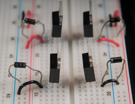
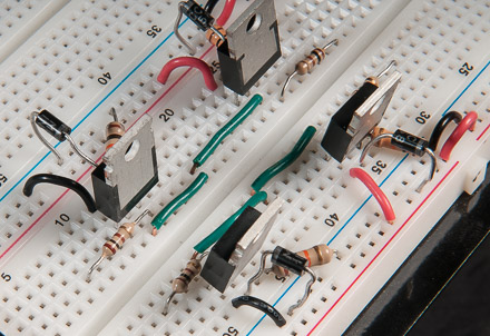
Side-view of high and low side MOSFETS with their source pins connected to appropriate rails of the motor circuit.
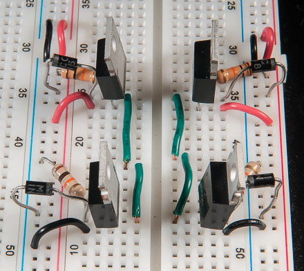
(Step #5) Tie the P-Channel gate pins "high":
In order to keep the "high-side" P-Channel MOSFETS in a default state of "OFF", connect their gate pins to the positive voltage supply of the motor circuit with 10kOhm resistors.
Side view of "pull-up" resistors connected to the gates of the "high-side" P-Channel MOSFETS.
(Step #6) Tie the N-Channel gate pins "low":
Likewise, the "low-side" N-Channel MOSFETS are kept in a default state of "OFF" by connecting their gate pins to ground via 10kOhm resistors.
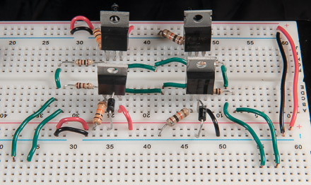
(Step #7) Form a "junction" between the drain pins of MOSFETS for each half of the H-bridge.
For both the left and right half of our H-bridge circuit, connect the drain pins of the "high-side" MOSFETS to the drain pins of the "low-side" MOSFETS. The "junction" where these connections meet is where the terminals of our motor will interface with the circuit. (This allows the current to take different paths through the circuit and consequently travel bi-directionally through the motor.)
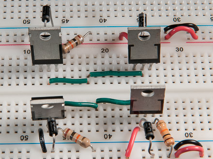
Side view of connection between drain pins.
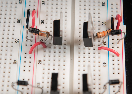
(Step #8) Connect 100 Ohm resistors to gate pins of "high-side" MOSFETS.
The signals from our MOSFET driver will connect to the gate pins via 100 Ohm resistors. When this pin is grounded by the signal coming from our MOSFET driver, the MOSFET will be switched "ON".
(Step #9) Connect 100 Ohm resistors to gate pins of "low-side" MOSFETS.
Similarly, our MOSFET driver will send its signals to the gate pins of the "low-side" MOSFETS via 100 Ohm resistors. Driving the gate pin high will switch the device "ON".
I extended the connections to the gate pins of all 4 MOSFETS to make things easier when it comes time to interface the H-bridge circuit with our MOSFET driver.
That's it.
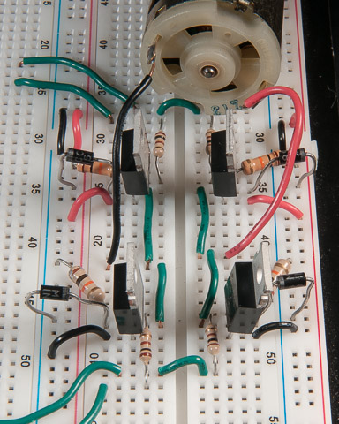
The leads of our DC motor will connect as seen to the left.
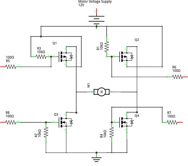
Schematic
Next we will wire up our MOSFET driver and interface it with the H-Bridge circuit.