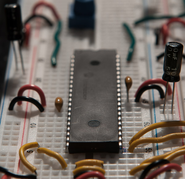
We have finally arrived at the point where we are going to interface the device that will act as the heartbeat for our DC motor H-bridge.
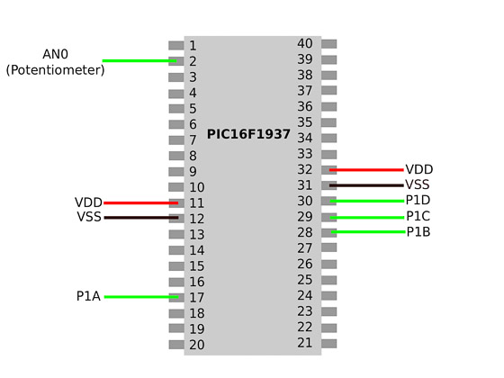
The Microchip PIC16F1937 is an 8 bit 40 pin microncontroller with 40kb of flash memory and 512 bytes of RAM. We will only be concerned with 9 pins. Of those pins, only 5 of them will be required to operate our H-Bridge. While 512 bytes of RAM seems laughable by today's standards, this is a pretty capable device with enough modules and features to fill up a 418 page Data Sheet.
We will be primarily dealing with the Analog to Digital Converter (ADC) and Capture/Compare/Pulse width modulation (CCP) modules
Pulse Width Modulation and speed control
Aside from allowing us to easily change the rotational direction of the motor, the microcontroller will also allow us to vary the speed at which it rotates. This is done through a technique commonly known as "pulse width modulation" (PWM). PWM is basically how we alter the on/off signals to our MOSFET switches in order to change the behavior of the motor. To understand pulse width modulation we need to be familiar with the concepts of: 1)frequency 2)period and 3)Duty cycle
Consider the graph below which compares voltage (v) as a function of time (t)
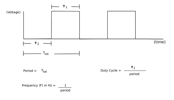
When we refer to the "period" of something, we are referring to one complete cycle of of particular characteristic that repeats. In our example above we see that the "characteristic" that repeats is the voltage turning on, turning off and then turning on again over a period of time. It does this repeatedly (infinitely) or until we tell it to stop by killing off the power source or by some other means. You could also say that the repeating characteristic is the voltage turning off, turning on and then turning off again depending on where you start measuring time on the x-axis. It really doesn't matter as long as you are consistent in choosing your points on the graph that show a beginning state and an ending state that represents one complete cycle.
You will often hear the term "frequency" used in any kind of signaling application. The unit for frequency is Hertz (Hz) and is simply 1 divided by the period. Furthermore, "pulse-width" is the duration of time that the voltage is in a high or "ON" state and is measured in units of seconds. Lastly, duty cycle is the percent of time that the voltage is in a high/ON state in reference to the entire length of the period.
Let's consider a specific example with some actual values...
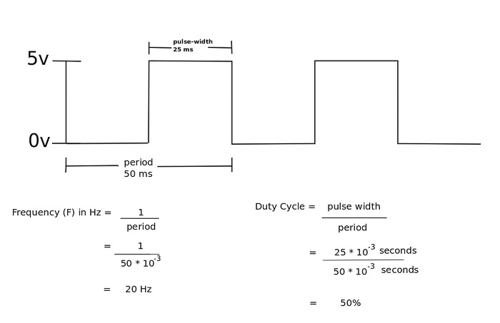
Above, we see that the "period" of time that it takes the voltage to go from 0v to 5v and back to 0v is 50 milliseconds. This frequency is simply 1 divided by (50 * 10^-3) seconds or 20 Hz. The choice of frequency depends on the motor being used. At certain frequencies, the electric motor will exhibit a whining or ringing sound that can be removed by altering your frequency. You must also ensure that the frequency does not exceed the switching speed of your MOSFETS. (Once again consult the data sheet). We will revist this when I explain the code used to adjust the frequency output of our PIC microcontroller.
You also notice that we have a 50% duty cycle due to the fact that our pulse width is 25ms compared the the period length which is 50ms. What this means is that for each period of time, the MOSFET switch will be turned on half of the time and turned off for the remaining 50% of the time. If the frequency is at a high enough speed to remove any "jittering" or perceptable switching of the MOSFET, it means that the motor will run at a speed that is equivalent to 50% of its power supply. So if our motor is connected to a 12v circuit, a 50% duty cycle allows it to run as if it were powered by 6 volts. A 25% duty cycle (12.5ms) means it would run at a speed comparable to a 3v power supply and etc..
Now that we have briefly explained the concepts of PWM, lets quickly assemble the circuit for our microcontroller. This is prety quick and straight forward and most likely something you have done before, but here's how I did it.
(Step #1) Connect a power supply switch and indicator light:
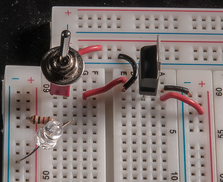
Creates a way to selectively turn power to the logic circuit on or off. The LED is another quick and easy way to visually confirm the state of the power to the circuit. A 7805 voltage regulator is used to maintain a steady 5v to the circuit.
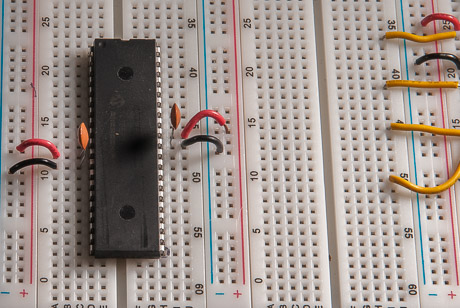
(Step #2) Connect ground and power pins of microcontroller with 0.1uF capacitors.:
(Step #3) Connect potentiometer to Analog input pin #0 (AN0):
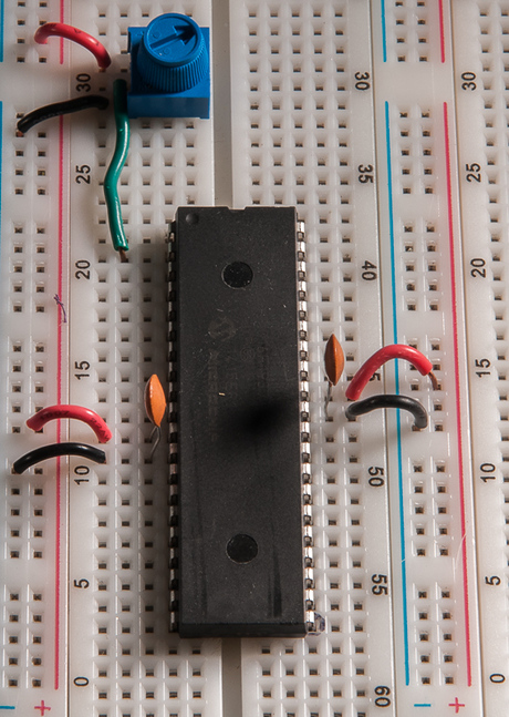
We will convert the analog signal from the potentiometer into a digital signal that controls the speed and direction of the DC motor. The AN0 pin (pin #2) of the PIC16F1937 is one of several pins that can be configured as either analog input or standard digital I/O pins.
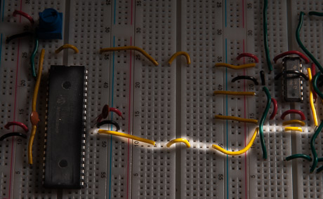
(Step #4) Connect P1A (pin#17 of microcontroller unit (MCU)) to input #1 of MOSFET driver):
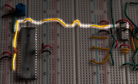
The signal output by PIA of the MCU will control the upper-right MOSFET of the h-bridge.
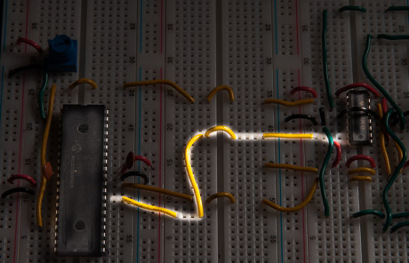
(Step #5) Connect P1D (pin #30 of (MCU)) to input #4 of MOSFET driver):
The signal output by P1D of the MCU will control the lower-left MOSFET of the h-bridge.
(Step #6) Connect P1B (pin #28 of (MCU)) to input #2 of MOSFET driver):
The signal output by P1B of the MCU will control the lower-right MOSFET of the h-bridge.
(Step #7) Connect P1C (pin #29 of (MCU)) to input #3 of MOSFET driver):
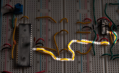
The signal output by P1C of the MCU will control the upper-left MOSFET of the h-bridge.
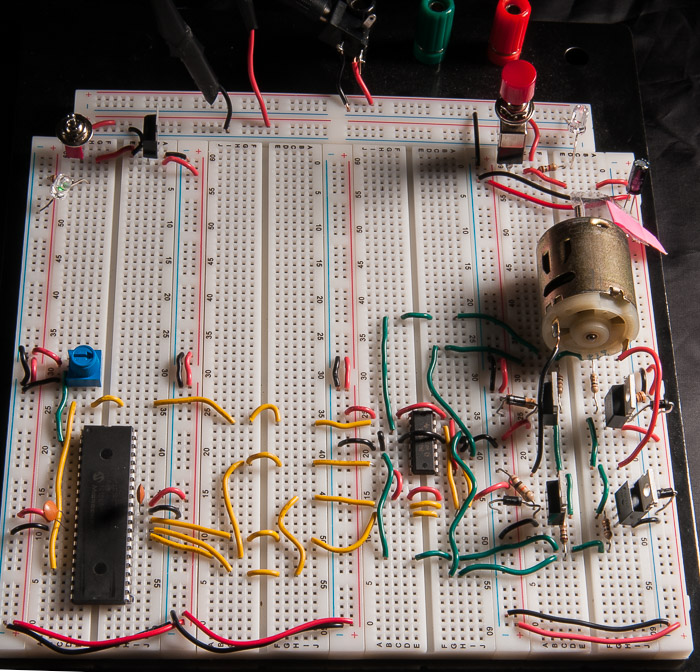
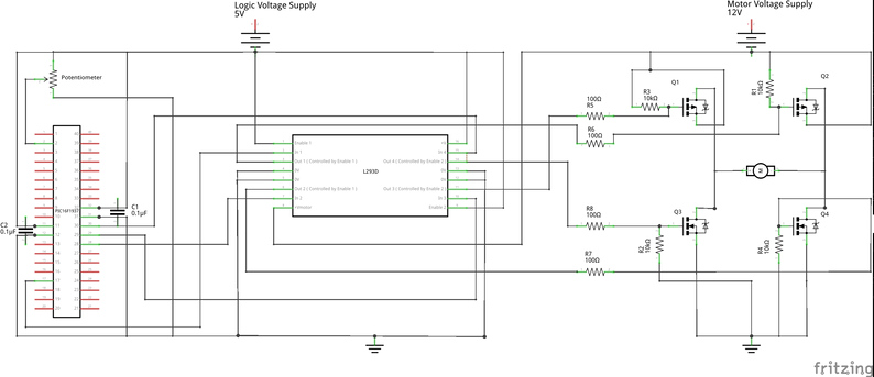
At long last we have completed the entire circuit:
Schematic
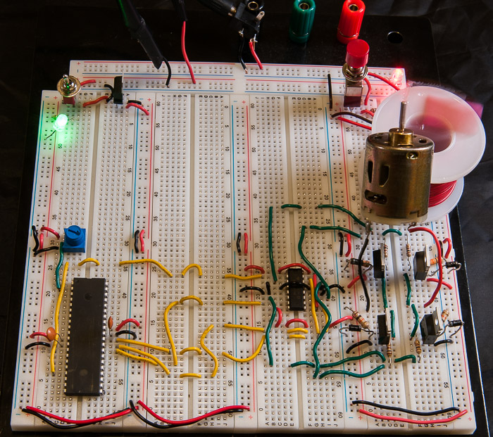
Motor in action.
Next we will explore the microcontroller code required to perform the analog to digital conversion (ADC).
Up next: Microcontroller code (Analog to Digital Conversion)