Now that we have the actual H-bridge circuit put together, we need to also assemble the driver circuitry. The main purpose of this "driver" circuit is to boost the 5 volt signals coming from the microcontroller to the 12 volts we need to switch the N-Channel devices "ON".
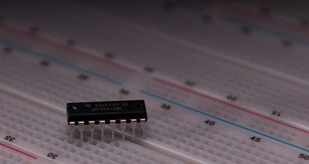
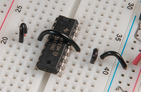
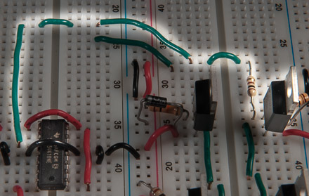
(Step #1) Place the driver IC in the bread board:
It's helpful to have the pin-out diagram handy when wiring any IC device. Also, most IC's have a u-shaped notch at one end that is represented in the datasheet diagram. This helps to ensure correct orientation when reading/connecting the pins. The pin diagram can be found in the driver Data Sheet
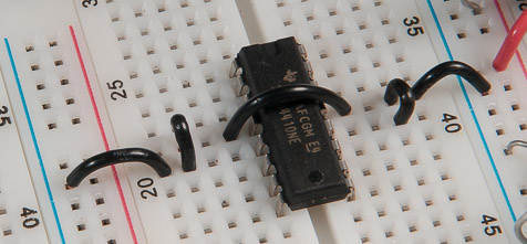
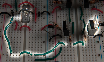
(Step #2) Connect ground pins (3 and 4) together:
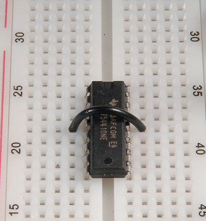
The grounding of this device gave me quite a few headaches that weren't readily solved by reading the datasheet. The trick I found that eventually solved the problem required tying all of the ground pins to both ground of the logic circuit and ground of the motor supply. I honestly don't know if this was the best way to go about it, but it was the only way I could get the MOSFETS to reliably switch completely on. We will do just that in the next couple of steps.
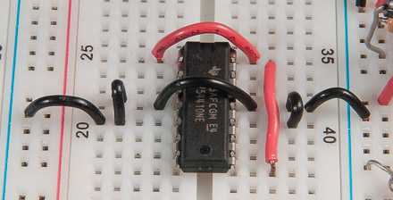
(Step #3) Connect pins 4, 5, 12 and 13 together:
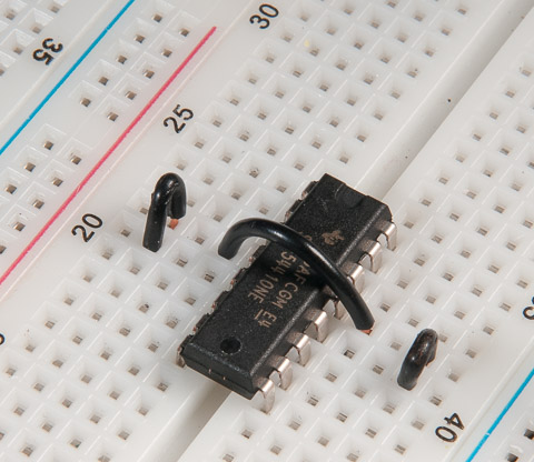
All of the four ground pins are now connected together.
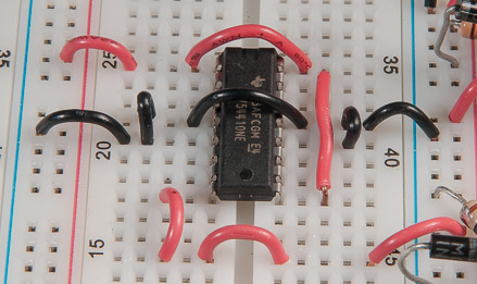
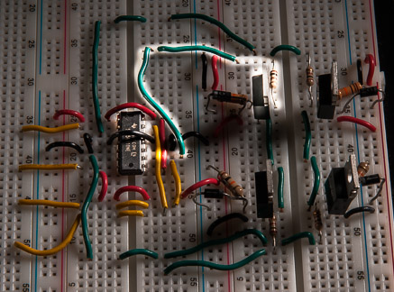
(Step #4) Connect ground pins to the ground rail of motor circuit...
(Step #5) ...and also to the ground rail of the logic circuit:
The driver's ground pins now have a common ground between the logic and motor circuit.
(Step #6) Connect the enable pins (1 and 9) and logic supply voltage pin (#16) together:
The "enable" pins require 5v for each half-bridge driver to be active. If they are grounded or left floating the device won't work. The logic supply voltage will also be 5v. Therefore connect these three pins together.
(Step #7) Connect enable and logic voltage pins to 5v and connect device voltage pin to 12v:
Connect the pins that were joined together in step #6 to the positive rail of the logic circuit (on left side of frame). Connect the device voltage pin (#8) to the positive voltage rail of the motor circuit. The voltage level that is output by this driver is determined by the voltage on pin #8.
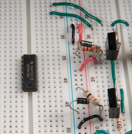
(Step #8) Connect output 1 (pin #3) to gate of upper right P-Channel MOSFET:
This will control the switching of our right "high-side" MOSFET.
(Step #9) Connect output 2 (pin #6) to gate of lower right N-Channel MOSFET:
This will control the switching of our right "low-side" MOSFET.
(Step #10) Connect output 3 (pin 11) to gate of upper left P-Channel MOSFET:
This will control the switching of our left "high-side" MOSFET.
(Step #11) Connect output 4 (pin 14) to gate of lower left N-Channel MOSFET:
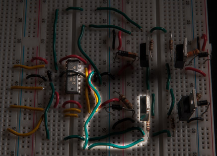
This will control the switching of our left "low-side" N-Channel MOSFET.
(Step #12) Extend the input pins for the MOSFET driver (yellow wires):
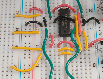
Just makes things a little easier when we connect our microcontroller to the driver.
Driver circuit is now complete.
Schematic
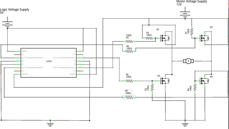
We have sucessfully wired up the circuit that will translate our 0 and 5 volt signals coming from the microcontroller to 0 and 12 volt signals that will open and close the MOSFET switches. Our next step will involve connecting the microcontroller to the driver circuit.