
So, we have established that manually activating the switches on the H-Bridge by hand would not be an ideal application of the circuit. Enter the transistor...
The first "point contact transistor" was developed in the U.S in 1947 by John Bardeen and Walter Brattain at AT&T's Bell Laboratories in New Jersey. This tiny device revolutionized life as we know it and can be found in nearly every single electronic product made in our lifetime. It's smaller physical size (relative to the vacuum tubes it replaced) enabled the creation of ever-more complex logic circuits. To say that this device resulted in the exponential growth of computing power over the last 60 years would be an understatement. It is widely considered to be one of the greatest inventions of the 20th century. In short, you can thank the transistor for the digital world we now we now live in. Our H-bridge is one of many countless applications for this device.
There are numerous types of transistors out there, but they all basically work on the same principle in terms of acting as a switch. A signal is output onto one pin which switches the device on and allows current to flow through the other two pins. With a bipolar-junction-transistor (BJT), a certain amount of current is needed on the base pin of the transistor in order to turn it on. A MOSFET (Metal Oxide Semiconductor Field Effect Transistor) acts in a similar manner but requires little to no current on its "gate" (basically the same as "base pin") and only requires voltage above a certain threshold value to turn on.
While either a BJT or MOSFET could be used with our h-bridge, a MOSFET is a better choice due to the fact that little to no current flows through the gate pin. This is important because it helps to isolate the logic circuit being used to drive the transistors from the circuit that is powering the motor. A large enough current draw from a typical 5 volt logic circuit can have negative consequences on its operation.
There are also different types of MOSFETS called "Depletion" and "Enhancement" types. "Depletion" type MOSFETS are normally "on" by default whereas "Enhancement" types are normally "off" by default. We will be using Enhancement type MOSFETS in our demonstration. Along with Enhancement type MOSFETS, we also need to concern ourselves with two more things, P-Channel and N-Channel MOSFETS.
N-Channel Enhancement Type MOSFET:
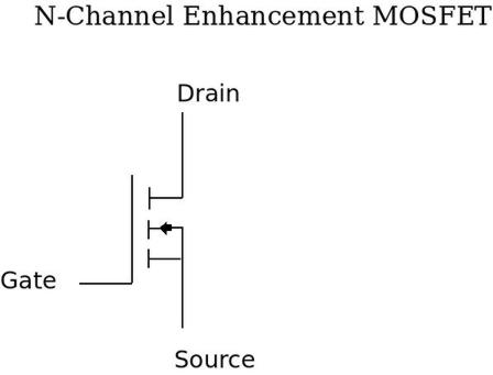
The N-Channel MOSFET shown above is controlled through the "gate" pin. When a positive voltage is applied here (relative to the voltage on the source pin), the device is turned on. When using MOSFETS in an h-bridge configuration this is the trickiest thing to wrap your head around and is the source of endless frustration at first. The gate voltage needs to be higher than source by a certain amount to fully switch it on. If it isn't above the source-voltage by a high enough amount, it will only partially open and you will wear it out prematurely if you run it in this state for a long enough time. Be sure to consult the datasheet of your particular MOSFET as this can vary. (The datasheet for our Fairchild Semiconductor FQP30N06L N-Channel MOFET can be found here): Fairchild N-Channel
The Confusing Part:
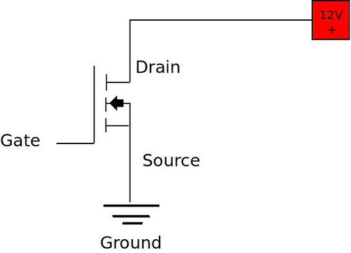
Remember when I said this gets confusing at first? Well, when when a single N-channel enhancement type MOSFET is used by itself to switch a single load (like a motor) on/off, its source pin is connected directly to ground. If ground is considered to be 0 volts in this example, then we simply send a voltage to the gate pin that is higher than the threshold amount. If the motor circuit is a 12 volt system then 12 volts on the gate will suffice for our particular MOSFET.
However, if we are using N-Channel MOSFETS as switches A and C in the diagram below:

we notice that the source pin of our MOSFET isn't connected directly to ground but rather to one of the motor terminals. If the motor is already conducting (due to the other high side switch "A" being on) and we need to reverse direction, it means that the source voltage on MOSFET "C" is going to be at the same potential as its drain pin (let's say 12v for this example). In other words, it isn't zero volts (or what we commonly consider ground). The MOSFET source pin is effectively "grounded" to 12 volts which means that in order to turn it on we need a voltage source greater than 12 volts on the gate pin. If we are limited to a single 12 volt supply for our motor circuit then the only way to do this involves more complicated circuitry like "boot-strapping" and "charge-pumps" using additional capacitors. The N-Channel MOSFETS on the "low side" (B and D) of the H-bridge are relatively simple to address since their source pins are connected to ground.
To make life easier, we introduce the P-Channel "Enhancement-type" MOSFET.
P-Channel Enhancement Type MOSFET:
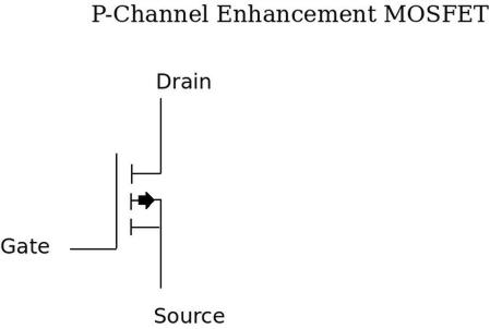
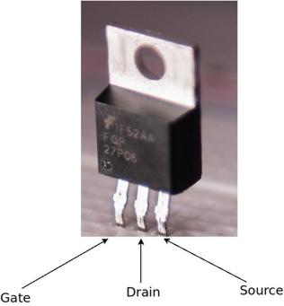
Fairchild P-Channel (FQP27P06) Data Sheet
The P-Channel Enhancement Type MOSFET shown above is also controlled through the "gate" pin. The difference is that a negative voltage on the gate pin (relative to the voltage on the source pin), turns the device "on". This is opposed to the postive voltage required on the gate pin of an N-Channel device. Using a P-Channel Enhancement Type MOSFET as the "high-side" switches in an H-bridge is ideal in this regard due to the fact that we don't have to be worried with increasing the voltage beyond the nominal voltage of our motor circuit in order to switch the device on. Instead, we only need to drive the gate pin to ground in order to switch the device on.
This can be accomplished by simply connecting the gate pin to a "pull-up" resistor and allowing your logic circuit to ground it (logic level 0 signal) when the desired state of the switch is "on". Inversely, the gates of the N-Channel MOSFETS will be grounded with "pull-down" resistors and your logic circuit with send a "high" (logic level 1) signal to the pin to turn it "on."
There is much more to discuss about MOSFETS/transistors than I have covered here, and my brief explanation doesn't really do the subject justice. If none of this makes sense at first, don't worry (it didn't to me either.) It really only begins to sink in when you put everything on a breadboard and start to see what works and what doesn't. Take full advantage of the data-sheets and other online resources as well.
It's important to note that we must come up with a way to drive our MOSFETS. With very low powered motors it is possible to drive them directly from a microcontroller in the unlikely scenario that the motor is powered from the same voltage source as your logic circuit. This usually won't be the case however as often times you will want to use a motor that requires voltage and current levels much higher than a typical 3v or 5v logic circuit can handle. In such a situation, we need a way to boost the 5v signal (binary "1") coming from the logic circuit to whatever threshold voltage levels are required to switch the MOSFETS on. This is what is commonly called a MOSFET driver and there are many options available to do this. Next we will discuss what I used to drive the MOSFETS in my H-Bridge circuit.