
The last two pages of this tutorial guided us through the process of configuring the registers associated with the ADC and PWM modules. This essentially set up the "environment" of the microcontroller in a manner that allows us to accomplish our stated goal of having directional and rotational speed control of our DC motor. The "Main loop" section of our code will reiterate in an infinite loop. During this time it continually samples the result of the Analog to Digital conversion and modifies the ECCP module accordingly. Three main things will be accomplished inside the main loop:
- 1) ADC process will be initialized.
- 2) The appropriate rotational direction will be determined based on the ADC conversion.
- 3) The appropriate rotational speed will also be determined based on the ADC conversion
Initializing the ADC Process:
If you recall from the ADC portion of this tutorial, bit #1 of the ADCON0 register starts the ADC process. However, once the conversion process is started, we need to wait for it to complete before proceeding forward. Since this bit is automatically cleared by the MCU once the conversion is done, we can simply poll the bit and proceed onwards once it is cleared.
banksel ADCON0
bsf ADCON0, GO
waitAdc
btfsc ADCON0, NOT_DONE
goto waitAdc
You will notice that the include file allows us to replace the actual bit number with the words "GO" and "NOT_DONE". This can make it more obvious as to what your code is doing when reading it. Either method is suitable however. (Ex: bsf ADCON0, GO is the same as bsf ADCON0, 1)
Determining Motor Direction:
Also recall that we want to use the potentiometer to control the direction of the motor. Half of the rotation of the knob of the potentiometer will correspond to forward and the other half reverse. Since the ADC conversion value can be any integer between 0 and 255 (which is held in the ADRESH register), we can simply denote any value <= 127 as corresponding to a reverse direction and any value > 127 a forward direction. If you are familiar with your binary numbering system, then you know that there is a simple way to check for this. With an 8-bit register, the most significant bit (MSB) will be set (1) for any value greater than 127 and cleared (0) for any value less than or equal to 127. Therefore, we can simply test the condition of this bit and then jump to the appropriate section of code where we will handle the adjustment of the duty cycle for speed control.
banksel ADRESH
btfss ADRESH, 7
goto mtrReverse
goto mtrFwd
Note: The last goto instruction for "mtrFwd" isn't really necessary as this section of code will be next in line to be executed anyway. I just put it in there to illustrate the point of making a conditional branch based on the condition of the MSB of ADRESH.
Duty Cycle:
The duty cycle of our pulses is determined by the CCPR1L register. This register also works in conjunction with the PR2 register that we configured in the last page of this tutorial. If you remember, we loaded the decimal value of 255 into the PR2 register which gave us a period length of 1.02 milliseconds. Well, the value that is loaded into CCPR1L simply represent a fractional amount of the value in PR2 and give us a corresponding duty cycle. At the beginning of each pulse, the preconfigured modulated output pin will go into its active state until the value of TMR2 reaches the value of CCPR1L. This process is continually repeated and creates a "pulse train" that controls the speed of our motor. For example, if CCPR1L contains the value 191, then we have a 75% duty cycle. (191 / 255 = 75%). We can continually sample the value of our AD conversion and adjust the value held in CCPR1L to give us variable speed control.
**As a side note (and without getting into great detail) due to the way the PWM module works, the maximum duty cycle we will be able to achieve is just over 99%. For our purposes, this is sufficiently close to the maximum speed of the motor.**
Determining Motor Speed (forward direction):
The forward speed of our motor will be determined by an analog input range of about 2.5v - 5.0v which will result in ADRESH values that range from 128-255 with 128=stopped and 255=full speed forward. Keep in mind that the voltage levels will deviate slightly from these "ideal" conditions due to the realities of varying tolerance levels of the components and slight voltage loss in the circuit. The maximum voltage I read on my AD conversion was 4.8 volts (instead of 5). In such a case, an analog input of 4.8 volts will still give us an ADRESH value of 255 since it represents the maximum possible input voltage (Voltage reference is the supply voltage). The math involved will still work out correctly in terms of a percentage that is converted to a duty cycle. So lets look at how we convert these values into an appropriate duty cycle.
It's easiest to think logically about how we can calculate this number in decimal notation and then see what "tricks" we can use with binary arithmetic to achieve the same result in as few instructions as possible. We are dealing with numbers ranging from 128 to 255 but we want to scale them to values ranging from 0 - 255. To do this we can simply subtract 128 from whatever number we have in ADRESH and then multiply it by 2 to get a duty cycle that works for the forward direction of our motor (as determined by the AD conversion process.) For example, lets assume we had the value 190 in ADRESH. If we subtract 128 from 190 (which equals 62), and then multiply by 2 (which equals 124), then 124 / 255 = 49%. Thus we would have a 49% duty cycle in the forward direction.
Since we are guaranteed that all ADRESH values in the forward direction will be greater than 128, subtracting 128 is as easy as clearing the MSB of the ADRESH value. This won't be necessary however since we will multiply by two by performing a left-shift instruction. With an 8-bit register, a left-shift will discard the MSB anyway and the subtracting of 128 will be performed by default. Therefore:
rlf ADRESH, w
banksel CCPR1L
movwf CCPR1L
left-shifts ADRESH and leaves the result in the working register. This number is then loaded into the CCPR1L register thus updating the duty cycle.
We also need to make sure that CCP1CON is still configured in "Full-Bridge-Forward" mode by clearing the P1M1 bit in the event that we have just transitioned from reverse to forward direction. Finally, we will reiterate this process by jumping back up to the beginning of our loop:
banksel CCP1CON
bcf CCP1CON, P1M1
goto mainLoop
Determining Motor Speed (reverse direction):
When adjusting the speed of our motor in the reverse direction, the range of ADRESH values will be from 0 - 127 with 127=stopped and 0 = full speed reverse. We again want to scale them to cover the range of values from 0 - 255 but with the duty cycle increasing as the the numbers in ADRESH decrease. In order to do this we can simply subtract the value in ADRESH from 127 and then multiply by two to get the correct duty cycle in the reverse direction. Again, the fact that we are working with 8-bit registers means that we can use some binary tricks to accomplish this in a few instructions. You may or may not be aware that the one's complement of a binary number is achieved by switching all of the zeros to ones and all of the ones to zero. This process is used in binary subtraction. If you complement the number in ADRESH and then left-shift it, the high bit is discarded and you get a duty cycle that works in the opposte manner as the one we calculated for the forward direction (Duty cycle will increase as ADRESH decreased from 127 to zero).
banksel ADRESH
comf ADRESH, w
rlf ADRESH, w
banksel CCPR1L
movwf CCPR1L
Also remember that we have to update the CCP1CON register by selecting "Full-Bridge-Reverse" mode by setting the P1M1 bit and then jumping back to the beginning of our main loop:
banksel CCP1CON
bsf CCP1CON, P1M1
goto mainLoop
As a visual reference, "Full-Bridge-Reverse" mode will look something like this:
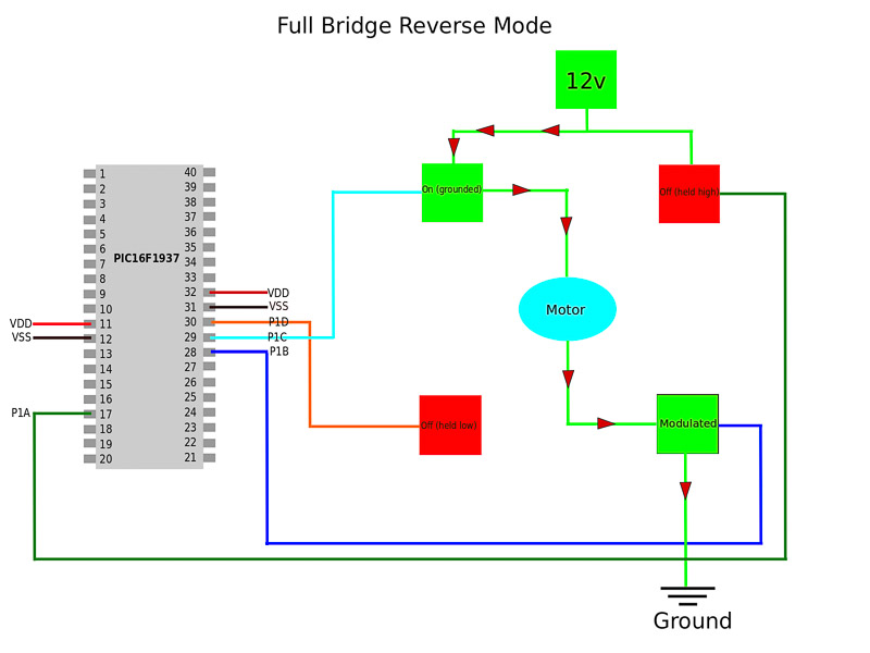
You will notice that with P1A and P1C configured as active low, P1C is active in the reverse mode (meaning that the upper left P-Channel MOSFET is pulled low and therefore turned on). P1A is inactive and left held high (turned off). P1D is configured as active high, and in reverse mode it is inactive and held low (turned off). Lastly, P1B is active high and modulated which gives us our variable speed control. The source code for the entire program can be seen below and is available via a downloadable text file in the datasheets section.
Up next we will take a look at some screen shots from the oscilliscope to better visualize what is happening.