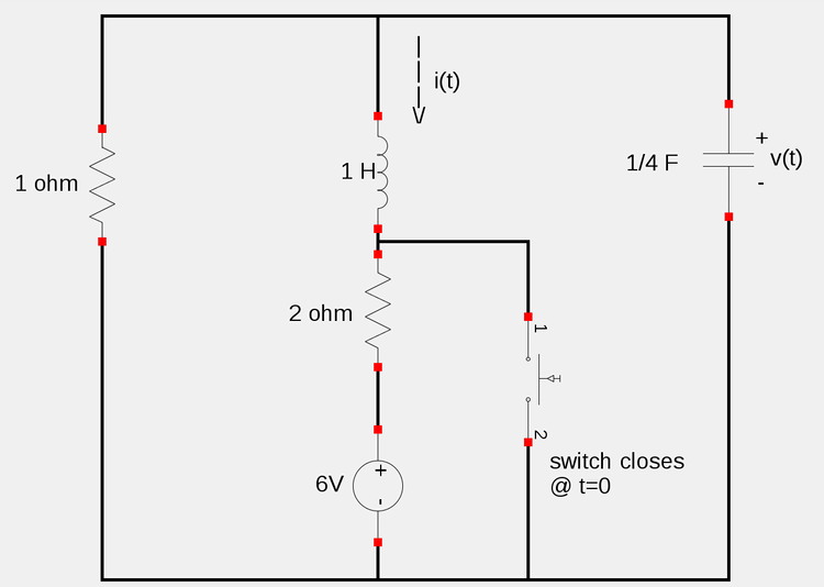
Given the following circuit, determine i(t), v(t) for t>0:
Step 1: Calculate initial conditions i(0), i'(0) and v(0)
First let's examine the conditions of the circuit at times t<0. We assume that the times are sufficiently less than t=0 so as to allow for steady-state conditions. During steady state conditions, the inductor acts as an short circuit and the capacitor acts as an open circuit. Furthermore, both the current through the inductor and the voltge across the capacitor can't change instantaneously such that:
$$i(0^-) = i(0) = i(0^+) $$
and:
$$v(0^-) = v(0) = v(0^+) $$
...where "-" and "+" represent times just before and after the closing of the switch
The circuit under such conditions is shown below:
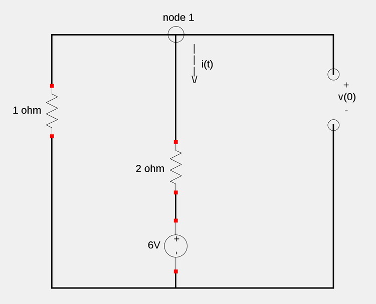
If we apply Kirchoff's Current Law (KCL) at node 1, we get:
$$\frac{v(0)}{1} + i(0) = 0 $$
$$i(0) = -v(0) \qquad(Equation \; 1) $$
Additionally, if we apply Kirchoff's Voltage Law (KVL) around the right-most loop, we get:
$$-v(0) + 2i(0) + 6 = 0 $$
$$v(0) = 2i(0) + 6 \qquad(Equation \; 2) $$
Substituting equation #2 into equation #1 gives us:
$$i(0) = -2i(0) - 6 $$
$$3i(0) = -6 $$
$$i(0) = -2A $$
We now plug in our newly determined value for i(0) into equation #2:
$$v(0) = 2(-2) + 6 $$
$$v(0) = 2V $$
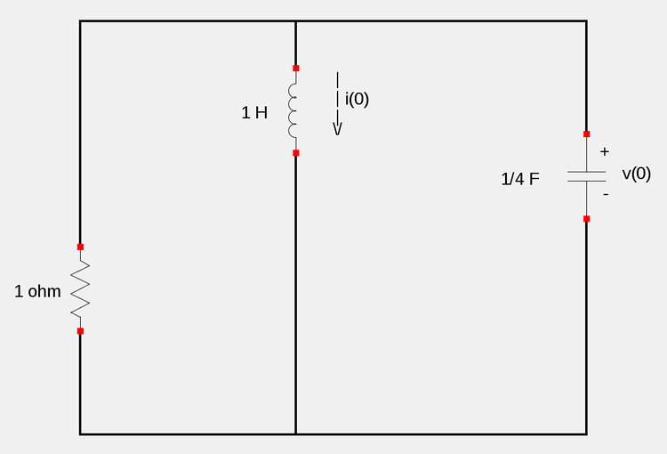
In order to determine i'(0), we consider the circuit at a time just after t=0:
Recall the definition of voltage across an inductor:
$$v_L = L\frac{di}{dt} = Li' $$
If we apply KVL to the right-most loop (the one that contains only the capacitor and inductor), we get:
$$-v(0) + v_L = 0 $$
$$v_L = v(0) $$
$$Li'(0) = v(0) $$
$$i'(0) = \frac{2}{1} = 2 $$
We have now determined the following initial conditions: $$i(0) = -2 $$ $$i'(0) = 2 $$ $$v(0) = 2 $$
Step 2: Obtain a differential equation for the circuit in its transient state:
Once the switch is closed at time t=0, the circuit resembles the following (short across voltage source and 2 ohm resistor):
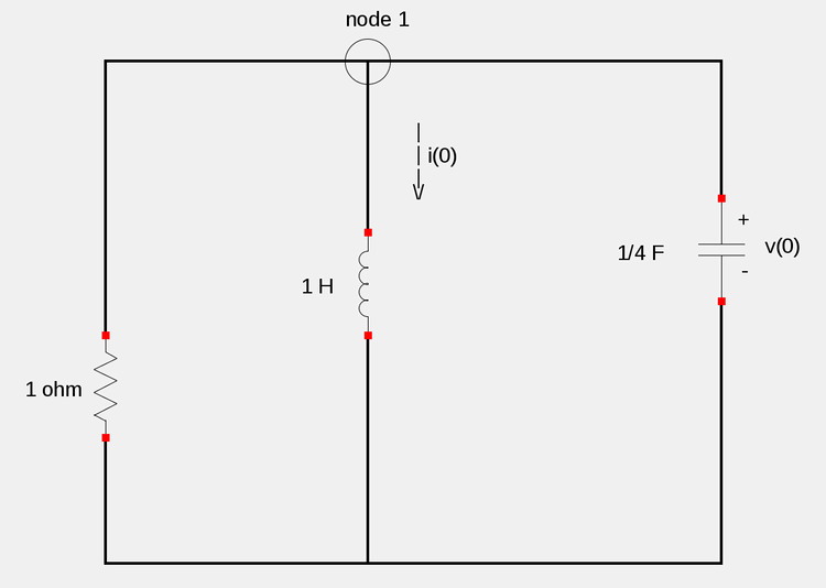
Recall the definition of current through a capacitor:
$$i_C(t) = Cv'(t) $$
...and apply KCL at node 1 gives us:
$$\frac{v}{1} + i + Cv' = 0 \qquad(Equation \; 3)$$
Note that:
$$v = v_L = Li' = i' $$
...and substitute this value for "v" into equation #3
$$i' + i + \frac{1}{4}i'' = 0 $$
Rearranging terms and multiplying through by 4 gives us:
$$i'' + 4i' + 4i = 0 \qquad(Equation \; 4)$$
Note that if we where to use the Annihilator Method, the two roots to our "characteristic equation would both be -2. From such information we would know that our circuit is critically damped. Instead, we will use the Laplace Transform Method
Step 3: Solve Equation #4 using Laplace Transforms
Start by taking the Laplace Transform of both sides of equation #4:
$$\mathcal{L}(i'') + 4\mathcal{L}(i'') + 4\mathcal{L}(i) = \mathcal{L}(0) $$
Using our Laplace Transform table we can expand as follows:
$$s^2\mathcal{L}(i) - si(0) - i'(0) + 4[s\mathcal{L}(i) - i(0)] + 4\mathcal{L}(i) = 0 \qquad(Equation \; 5)$$
Recall our previously determined initial conditions:
$$i(0) = -2 $$
$$i'(0) = 2 $$
...and plug them into equation #5
$$s^2\mathcal{L}(i) + 2s - 2 + 4s\mathcal{L}(i) - 4(-2) + 4\mathcal{L}(i) = 0 $$
$$\mathcal{L}(i)(s^2 + 4s + 4) + 2s + 6 = 0 $$
$$\mathcal{L}(i) = (-2s - 6) \Big(\frac{1}{s^2 + 4s + 4} \Big) $$
$$\mathcal{L}(i) = \frac{-2s-6}{(s+2)^2} $$
$$\mathcal{L}(i) = \frac{-2s}{(s+2)^2} - \frac{6}{(s+2)^2} $$
We now want to obtain an expression for i(t) by taking the inverse Laplace Transform of both sides of the equation.
$$i(t) = \mathcal{L^{-1}}\Big( \frac{-2s}{(s+2)^2}\Big) - \mathcal{L^{-1}} \Big( \frac{6}{(s+2)^2}\Big) \qquad(Equation \; 6)$$
In order to solve the two inverse Laplace Transform terms, we will make use of our table. When doing so you may notice that the term with the -2s in the numerator doesn't quite resemble any of the expressions. To change this, we must do some side work with partial fraction decomposition:
Side Work (Partial Fraction Decomposition):
$$\frac{-2s}{(s+2)^2} = \frac{A}{s+2} + \frac{B}{(s+2)^2} $$ $$-2s = A(s+2) + B $$ letting s=0: $$\qquad 2A + B = 0$$ letting s=1: $$\qquad 3A + B = -2 $$ Solving the system of two equations gives us: $$A = -2 $$ $$B = 4 $$ ...and we have: $$\frac{-2s}{(s+2)^2} = \frac{-2}{s+2} + \frac{4}{(s+2)^2} $$
Substituting the result of our partial fraction decomposition into equation #6 gives us:
$$i(t) = -2\mathcal{L^{-1}}\Big[ \frac{1}{s+2}\Big] + 4\mathcal{L^{-1}}\Big[ \frac{1}{(s+2)^2}\Big] - 6\mathcal{L^{-1}}\Big[ \frac{1}{(s+2)^2}\Big] $$
$$i(t) = -2\mathcal{L^{-1}}\Big[ \frac{1}{s+2}\Big] - 2\mathcal{L^{-1}}\Big[ \frac{1}{(s+2)^2}\Big] \qquad(Equation \; 7)$$
Now when we make use of our table, we see that the 1st term resembles item #2:
$$\mathcal{L^{-1}}\Big(\frac{1}{s+2} \Big) = e^{-2t} $$
...and the 2nd term resembles item #23:
$$\mathcal{L^{-1}}\Big(\frac{1}{(s+2)^2} \Big) = te^{-2t} $$
If we substitute these two terms into equation #7, we get:
i(t) for all t>0:
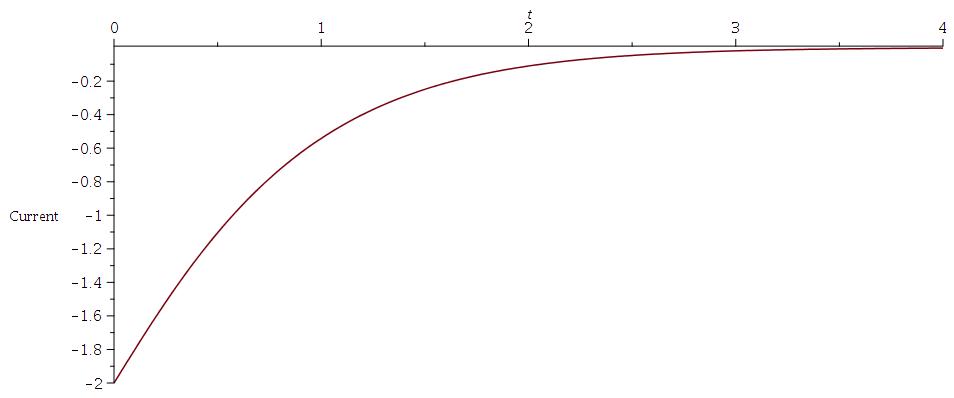
$$i(t) = -2e^{-2t} - 2te^{-2t} $$
In order to obtain an expression for v(t), we recognize that the capacitor is in parallel with the inductor and thus has the same voltage across it. Therefore, using the definition of voltage across an inductor, we get:
$$v(t) = v_C(t) = v_L(t) = L\frac{di}{dt} $$
$$v(t) = \frac{d}{dt}(-2e^{-2t} - 2te^{-2t}) $$
$$v(t) = 4e^{-2t} - 2(e^{-2t} - 2te^{-2t}) $$
We now have our expression:
v(t) for all t>0:
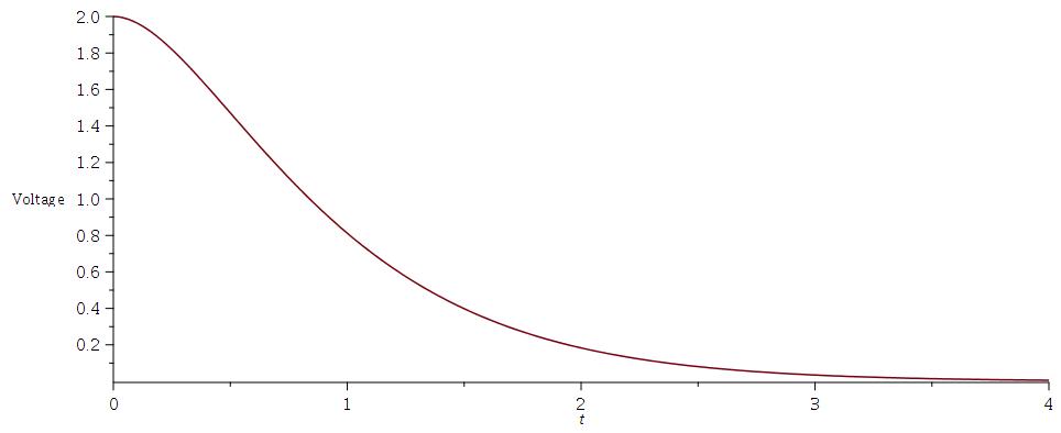
$$v(t) = 2e^{-2t} + 4te^{-2t} $$
Graphs of expressions for voltage and current , t>0
i(t), current through inductor:
v(t), voltage across capacitor:
Now that we have examined some of the more rigorous mathematics involved in RLC circuits, lets take a look at a somewhat more simplified method to solving second order circuits in general:
Continue on to Solving general 2nd order circuits...