When we talk about the step response of a series RLC circuit, we are referring to a situation where there is a sudden application of a DC source. Let's consider the following circuit shown below.
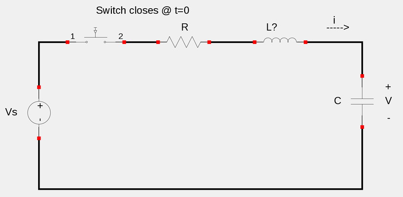
If we apply Kirchoff's Voltage Law (KVL) around the loop for the circuit at times t>0, we get:
$$Ri + L\frac{di}{dt} + V = V_s $$
...where our goal is to determine V. (The voltage across the capacitor). Recall that "i" (the current through the inductor) is expressed as:
$$i = C \frac{dV}{dt} $$
...and if we substitute this into our KVL equation and rearrange the terms, we get:
$$LC \frac{d^2V}{dt^2} + RC \frac{dV}{dt} + V = V_s $$
Now divide through by LC:
$$\frac{d^2V}{dt^2} + \frac{R}{L} \frac{dV}{dt} + \frac{1}{LC} V = \frac{V_s}{LC} \qquad(Eqn \; 1) $$
Equation #1 is a non-homogeneous second order differential equation that can be solved by either the Annihilator Method or by the Laplace Transform Method. You will notice that the coefficients of equation #1 are the same as for a source-free series RLC circuit with the main difference being that everything here is in terms of "V" instead of "i" and our equation here does not sum to zero. Essentially, the "characteristic equation" for the step response of a series RLC circuit is not affected by the presence of a DC source. For these step-response circuits, we will use the Laplace Transform Method to solve the differential equation.
Solutions to equation #1 have two components:
1) Transient Response (dies out with time)
$$V_t(t) $$
2) Steady-state Response (final value of V(t))
$$V_{ss}(t) = V_s$$
...where:
$$V(t) = V_t(t) + V_{ss}(t) $$
Just as with source-free series RLC circuit, there are three possible scenarios regarding solutions to equation #1. Note the following substitutions:
$$\alpha = \frac{R}{2L} $$
$$\omega_0 = \frac{1}{\sqrt{LC}} $$
$$\omega_d = \sqrt{w^2_0 - \alpha^2} $$
Case 1 (Overdamped)
$$\alpha \gt \omega_0 $$
Soultions will be of the form:
$$V(t) = V_s + Ae^{s_1t} + Be^{s_2t} $$
Case 2 (Critically Damped)
$$\alpha = \omega_0 $$
Soultions will be of the form:
$$V(t) = V_s + Ae^{- \alpha t} + Bte^{- \alpha t} $$
Case 3 (Underdamped)
$$\alpha \lt \omega_0 $$
Soultions will be of the form:
$$V(t) = V_s + Ae^{- \alpha t} cos(\omega_dt) + Be^{- \alpha t} sin(\omega_dt)$$
The constants A and B of our solution can be determined via the initial conditions V(0) and V'(0). Additionally, once we determine V(t) (the voltage across the capacitor), the current through the inductor (i) will be the same as the current through the capacitor since this is a series circuit. Therefor "i" will simply be:
$$i(t) = C \frac{dV}{dt} $$
...where "v" is the solution to our original differential equation (equation #1)
In the next page of this section we will work through an actual example and determine the complete response of a series RLC circuit.
Continue on to RLC step response example #1