Control Box Circuit
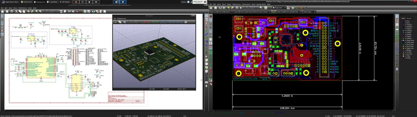
The circuit for the ROV control box is relatively simple and straight forward. I constructed this circuit with two boards. The "main" board sits inside the bottom housing of the control box and a smaller board is attached to the underside of the top panel of the control box. The two boards are connected with a ribbon cable that can be detached and allows for easier dissasembly. Additional features include an external RJ45 jack for communicating with the ROV via RS232 as well as an external RJ11 jack for updating the firmware of the MCU via In Circuit Serial Programming (ICSP). I started out with a simple breadboard circuit and added features/components one at a time as I got them to work correctly. I then proceeded to solder the circuit together using perf-board. Once I felt reasonably confident that my design was going to work, I drew up the schematic and PCB using KICAD. The actual construction at this moment is shown below :
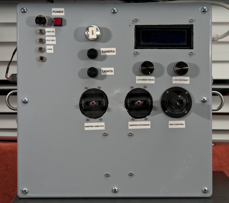
Top down view of control Box:
The following control box photos represent a continuous evolution of the design. With this in mind, you will see lots of "rough edges" due to various configurations that were abandoned or changed as time progressed.
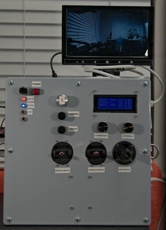
U-shaped brackets were added for use with a neck strap.
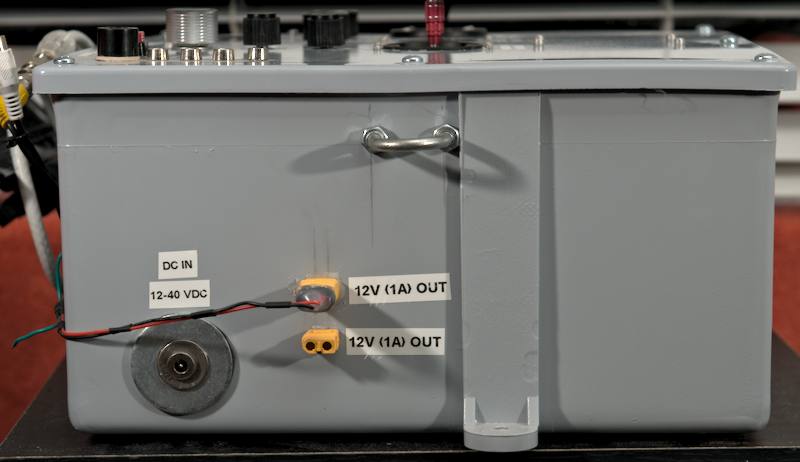
Side views of control Box:
An RJ45 jack is for the tether link while the RJ11 jack is used for firmware updates via a Microchip PICKIT 2,3 or 4. Two options are provided for video output (F-connector or BNC).
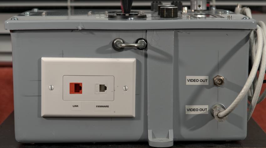
A barrel jack is used for connecting a power source to the control box. The regulated DC 12v output is for powering the mounted LCD screen (which displays analog video from the ROV camera.)
Interior view of control Box (Perf-board, Prior to LCD and video connections)
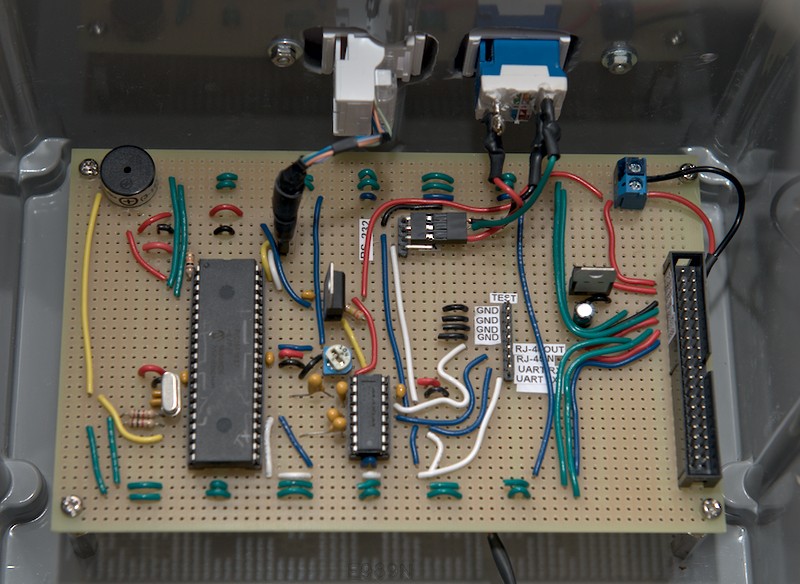
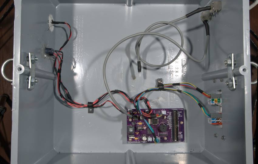
Interior views of control Box:
Here we see the PCB made from my design by Oshpark after I hand soldered the components. (with LCD and video connections added.) The two gray cables are for the video output that goes to the LCD screen. Here I am using the F-connector option and leaving the BNC cable disconnected.
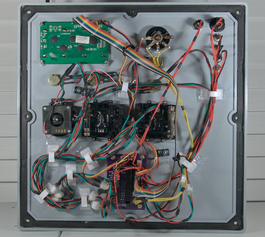
Inside of the top cover:
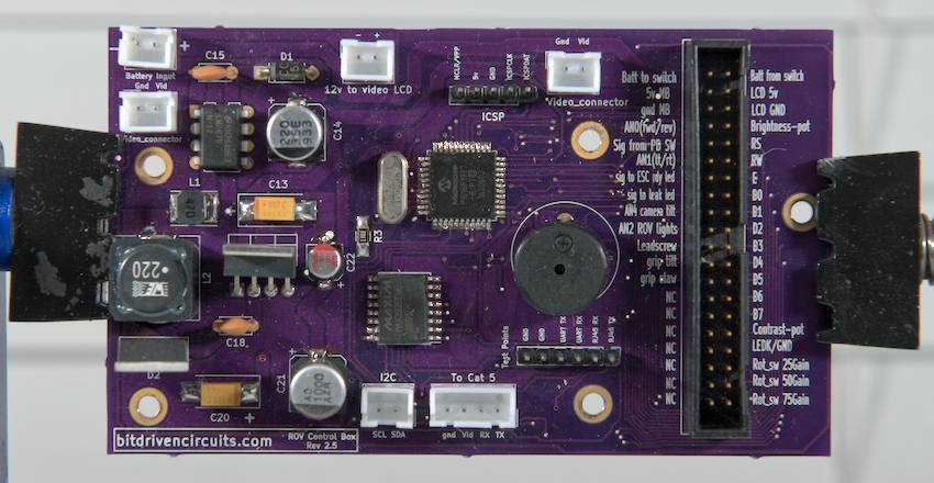
Main PCB (front)
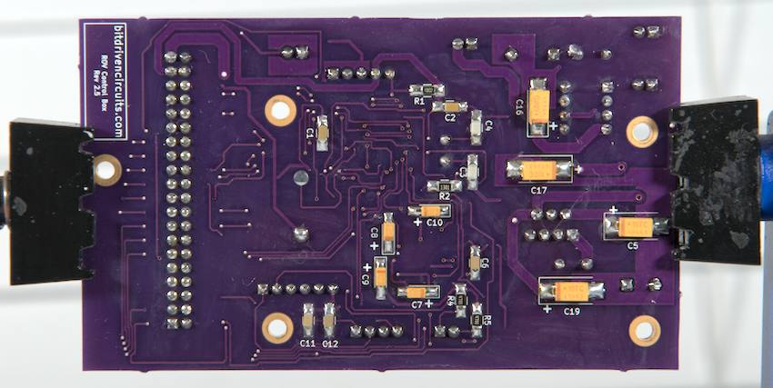
Main PCB (rear)
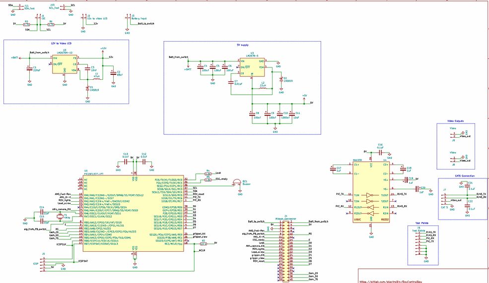
Main circuit board schematic:
Top panel circuit board schematic:
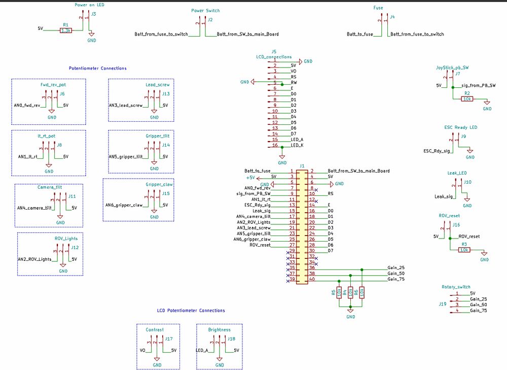
Top Panel circuit board Hi-Res Schematic
The schematics may come in useful once we get to the software section as it can help you visualize what is going on when we configure pins and transmit signals based on various inputs. Regarding the RS232 transceiver (made by Maxim Intergrated), it is relatively simple to hook up and the documentation in terms of capacitor values and pin connections can be found in the data sheet. The 20x4 LCD displays sensor information as well as any alerts (Leak detection, ESC initialization, battery voltage, temperature etc...).