(The information on this page references the GripperController.asm file.)
Interrupt Configuration
The firmware controlling the gripper arm is completely interrupt driven and nothing occurs inside the main loop of the program. There are two events that will trigger an interrupt:
- An I2C "start" condition
- An interrupt on change (IOC) for pins 0 and 1 of the PORTB register
These two interrupt conditions are enabled upon device startup with the following code:
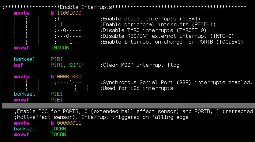
It is important to note that the limit switch hall-effect sensors are normally high (output is a 5V signal in the absence of a magnetic field) and drop low (0V signal) when a magnetic field is present. Since we want to trigger an interrupt upon a low signal, we need to configure the IOCBN register (as opposed to the IOCBP register) so that the interrupt service routine (ISR) is called when a falling edge is detected on pins 0 and 1 of PORTB.
I2C Interrupts
Communication betweeen the ROV and gripper arm controllers begins with the ROV controller receiving three data packets (via UART) from the surface. These three data packets are PWM values used to control the brushless motor driving the lead screw as well as the two servos found on the gripper mechanism. For each of the three data packets, the ROV controller does the following:
- Determines if the PWM value has changed since the last reception.
- If the PWM value is different, the appropriate command is sent to the gripper controller.
- The PWM value is sent to the gripper controller.
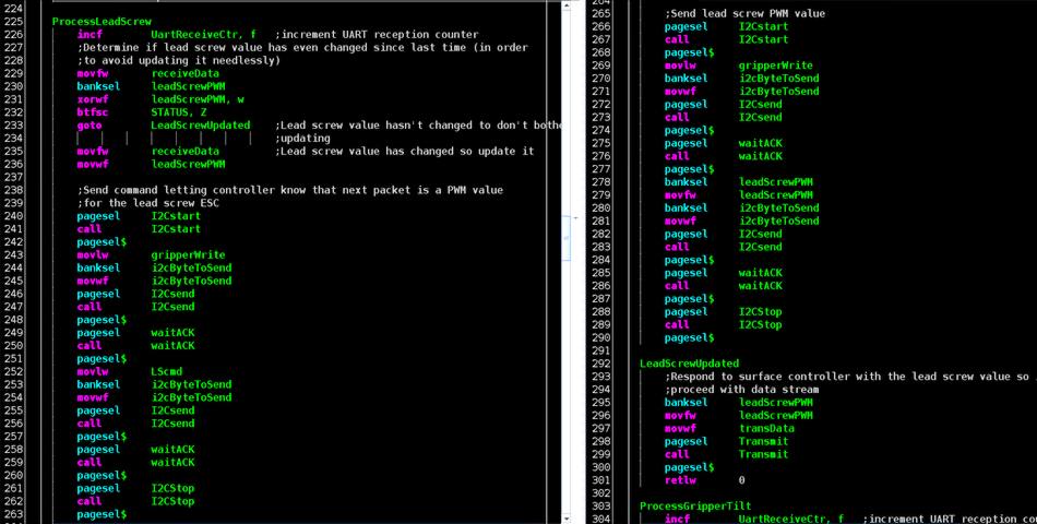
Step number one prevents the wasting of clock cycles by needlessly sending I2C packets when the PWM values have not changed (ie: the ROV operator is not pressing the gripper arm joysticks). Just as with the sections regarding the battery monitor and LED controller, this is not meant to be a "ground up" tutorial of the Microchip's implementation of the I2C protocol, but rather a brief overview of how it is used in this application. The ROV controller's role in communicating with the gripper arm is demonstrated in the code shown below. This particular screen-shot shows the portion relating to the PWM value being sent for the lead screw. (...and is found in the GripperController.asm file.)
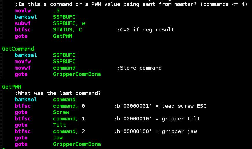
In terms of commands that can be sent to the gripper controller, there are three of them (shown below in terms of 8-bit binary numbers:
- 00000001 = PWM value for lead-screw ESC will be sent
- 00000010 = PWM value for the gripper tilt servo will be sent
- 00000100 = PWM value for the gripper jaws will be sent
Since commands are all going to be numbers less than or equal to 4 (and PWM values will always be larger than 4), the gripper controller checks the value of the I2C data packet and determines is the value is 4 or less. If it is, the command is stored in the variable named "command". When the next I2C packet is received it will be a PWM value (which is greater than 4). The gripper controller will receive it, check what the previous command was, and then jump to the appropriate section of code where the PWM value will be sent to either the lead-screw ESC or one of the gripper servos. This part of the process is shown below:
Continuing on with the lead-screw ESC example, we can see what happens when the lead-screw command was sent and the PWM value has been received:
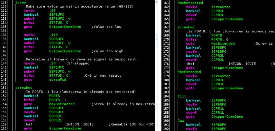
In the case of the lead-screw, the rotational direction of the PWM value is checked as well as the status of pins 0 and 1 of PORTB. If either pin is low it means that the lead screw is at the max extent of its range of motion (either completely retracted or completely extended). If either is the case, a "stop" PWM signal is sent to the ESC depending if the PWM signal received via I2C would cause to to be driven in a direction that is outside of the intended range of motion'.
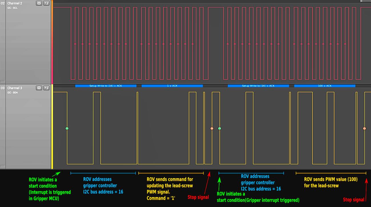
The following decoded logic logic analyzer capture shows the transmission sequence between the ROV and gripper controller as the PWM value for the lead screw is sent via I2C. In this case, a PWM signal of 100 causes the lead screw to extend at a relatively slow speed. (The maximum extension speed being 118.)
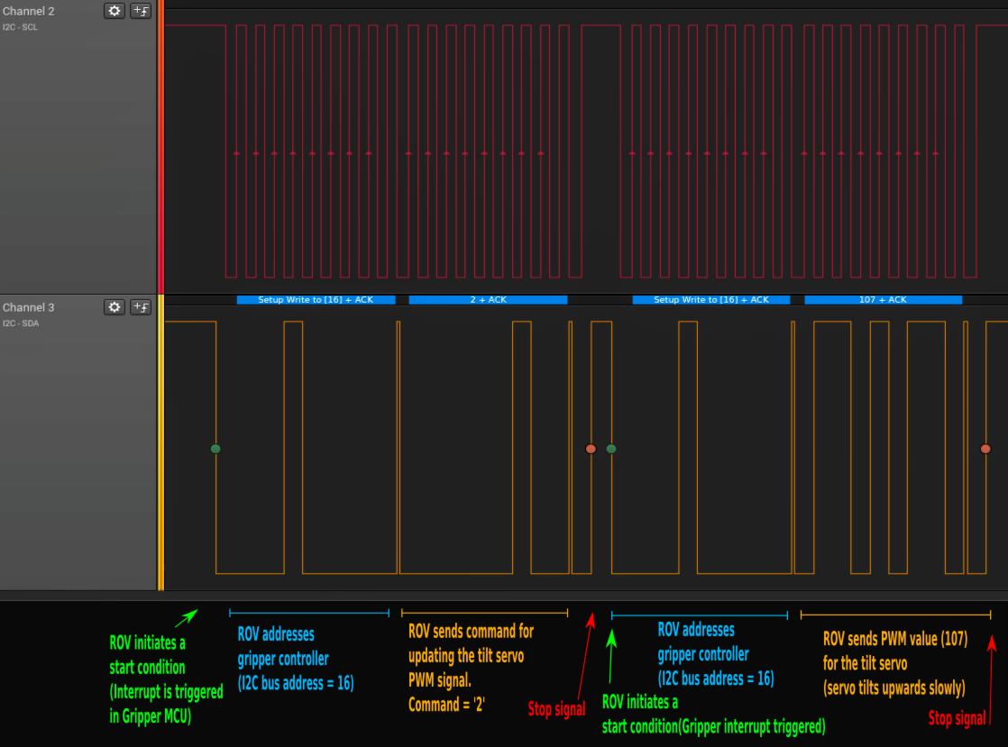
Below we see the sequence for updating the PWM signal sent to the servo controlling the gripper tilt:
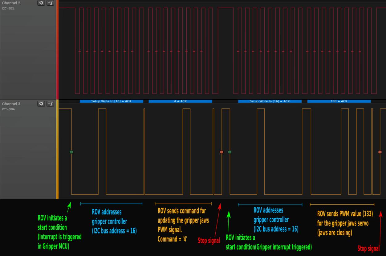
...and finally we see the sequence for updating the PWM signal for the gripper jaws:
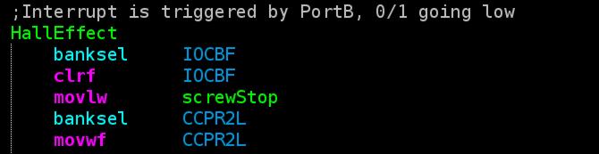
PORTB Interrupts
As was mentioned previously, an interrupt is also triggered on the falling edge of pins 0 and 1 of the PORTB register. Pin 0 of PORTB is connected to the hall-effect sensor that detects the fully extended position of the lead screw. Pin 1 of PORTB is connected to the hall-effect sensor that detects the fully retracted position of the lead screw. When either pin is pulled low, the interrupt service routine causes a "stopped" PWM signal to be sent to the lead-screw motor ESC: