
Schematic
Here is a brief overview of the circuit board found on the ROV. Perhaps the best way to start is with the schematic.
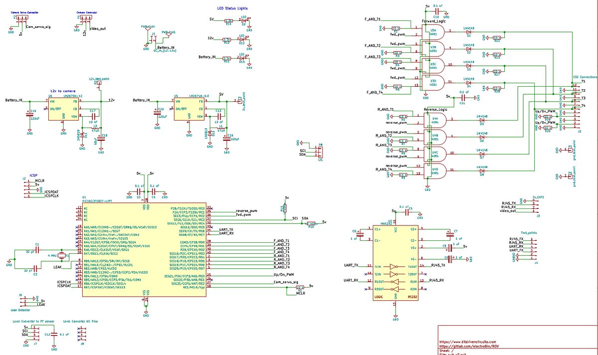
(A higher resolution version of the schematic can be found here )
Aside from the PIC16F1937, the three additional ICs on the board are the MAXIM RS232 transceiver as well as two quad AND gates. One of the AND gate ICs handles forward PWM signals and the other reverse. Being that there are four of these AND gates on each chip, each of the 4 corner mounted thruster motor ESCs is connected to both a "forward" AND gate and a "reverse" AND gate. Since only two different PWM signals are ever needed at one time (not including up/down movement) the AND gates are a simple way to direct these signals to the appropriate thruster ESC.
The board was initially constructed with bakelite/perfboard material and mounted on a tray made by Blue Robotics. It is designed to fit neatly inside the 4" diameter waterproof acrylic housing.
Afterwards, I designed a PCB using kicad and had it fabricated by Oshpark.
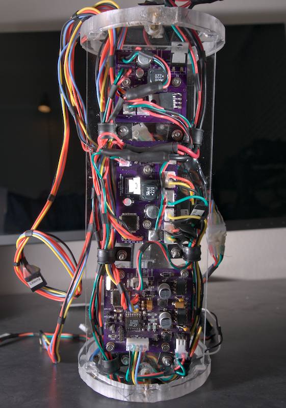
PCB (front-side):
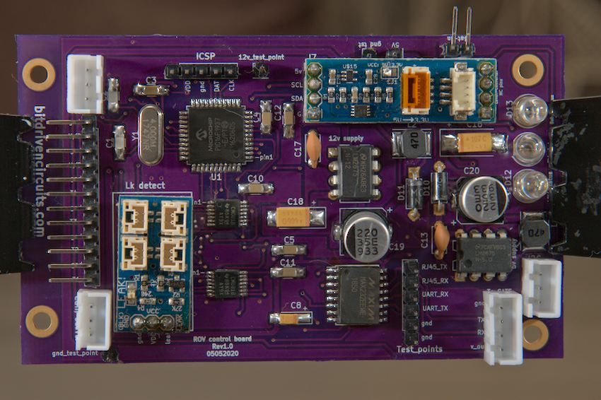
(The version number on the front side of the PCB is incorrectly labeld as 1.0. It should be labeled as 1.1)
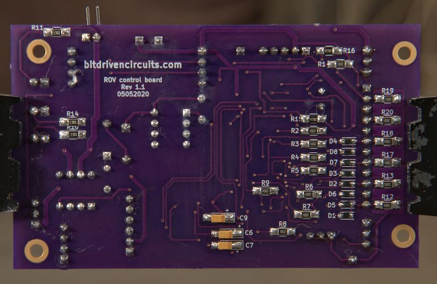
PCB (back-side):
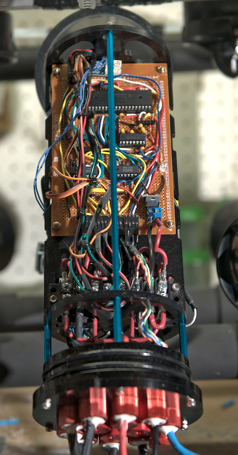
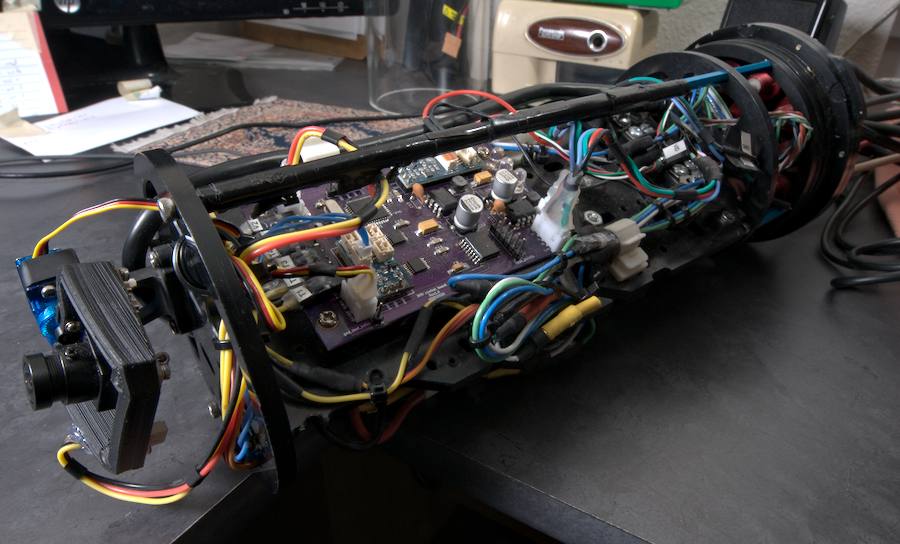
PCB mounted on electronics tray:
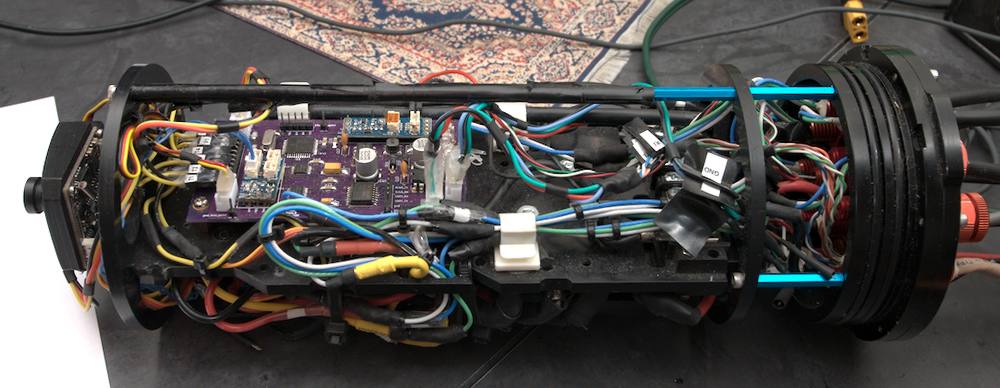
The underside of the tray contains all of the ESCs and corresponding connections. 15 amp protective fuses are also used for the ESCs and are mounted in an ATC style fuse block sourced from a local auto parts store.
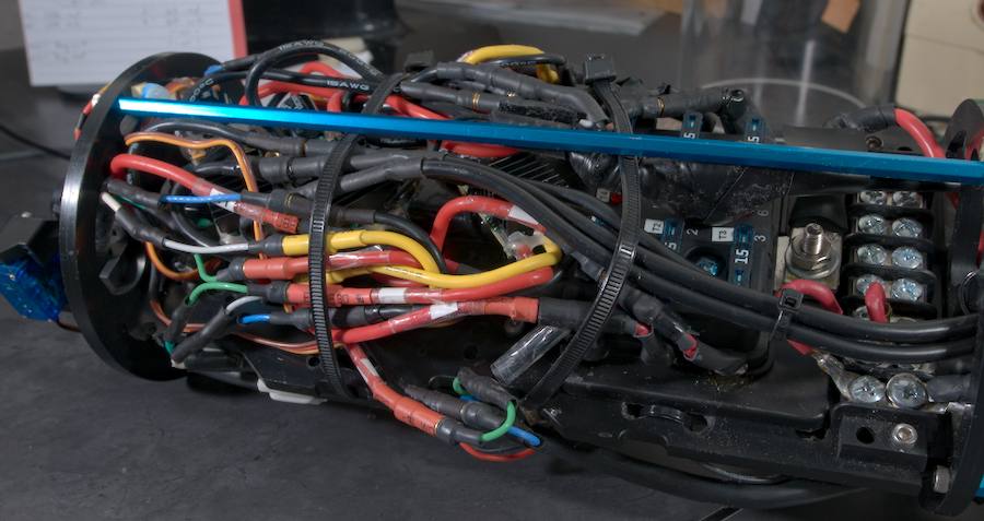
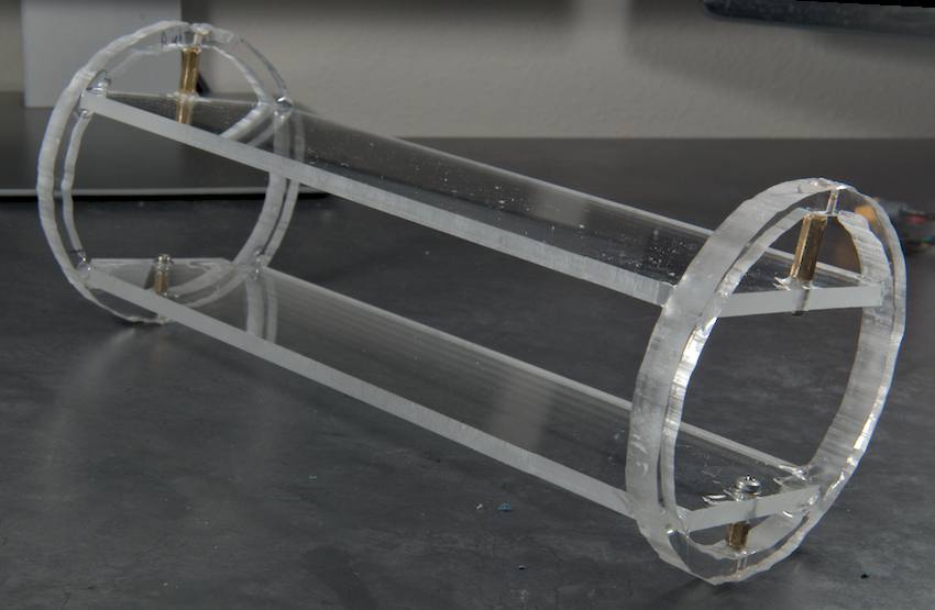
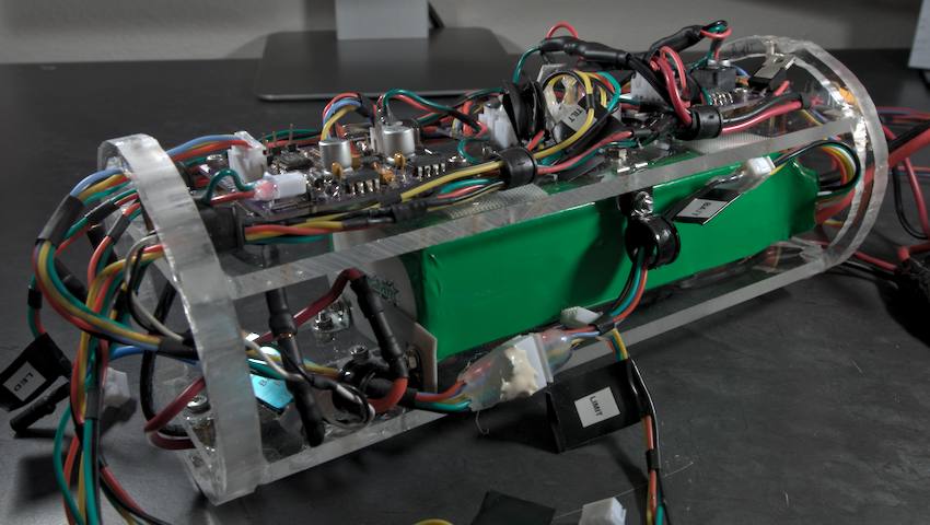
Battery Compartment
The other watertight compartment houses the lithium ion battery as well as the control boards for the battery monitoring circuitry, LED controller, and gripper arm controller. I used some scrap pieces of acrylic (Plexiglas) to make a tray to hold all of these items
Components added:
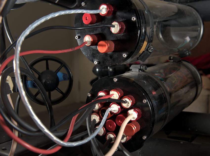
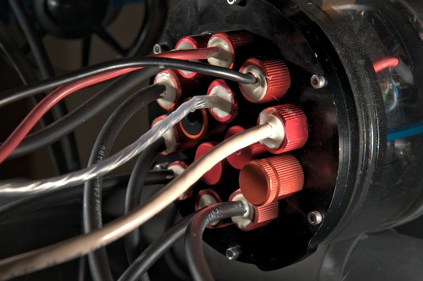
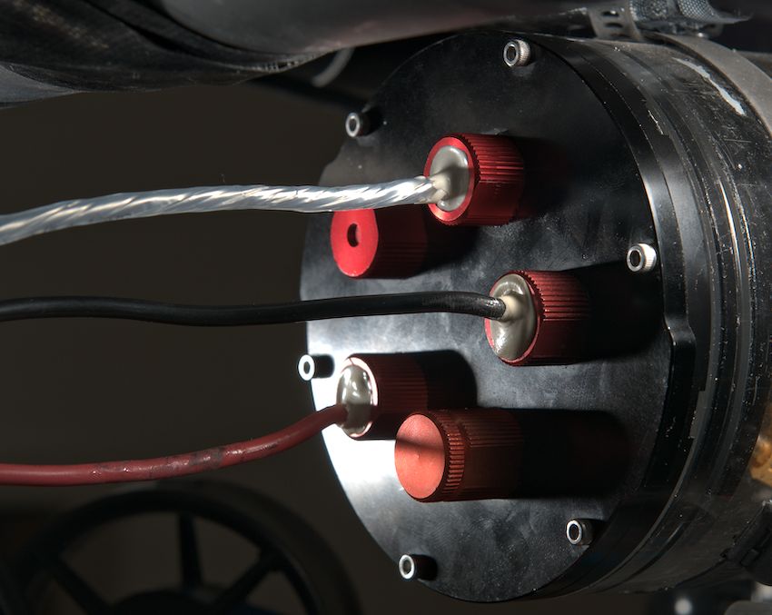
All wires entering the water-tight compartments are sealed with the Blue Robotics pass-through penetrators and Loctite marine epoxy. There is also a pressure release valve for each housing. This allows for pressure equalization prior to (or after) submerging. The lower compartment also contains the temperature/pressure sensor (penetrator is black in color). The silver colored shielded cable is for I2C communication between the battery monitoring circuitry and the main MCU. The plastic coating on this particular cable is very brittle and not well suited for an outdoor/marine environment. In the future I will be looking for a better solution. (Edit: this cable has been replaced.)
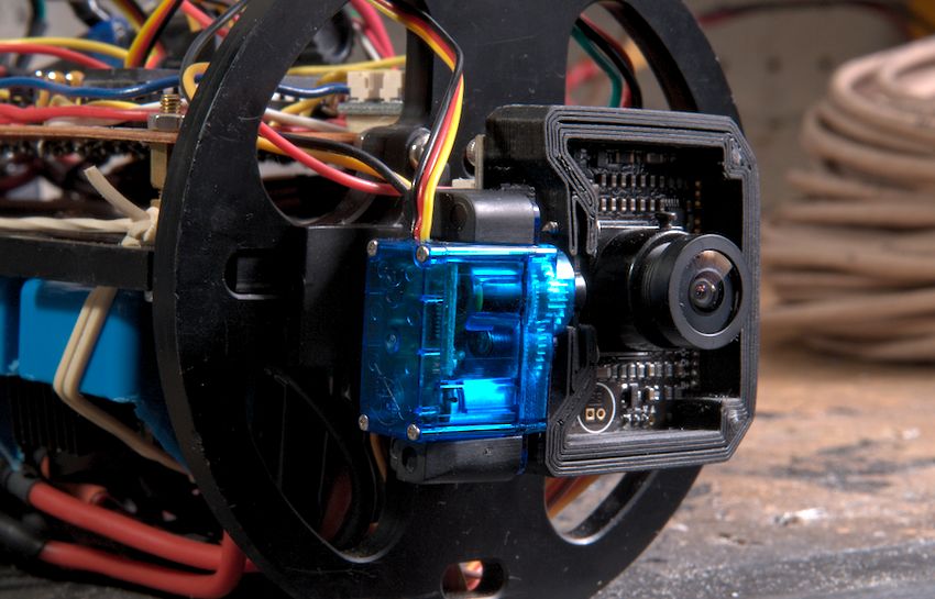
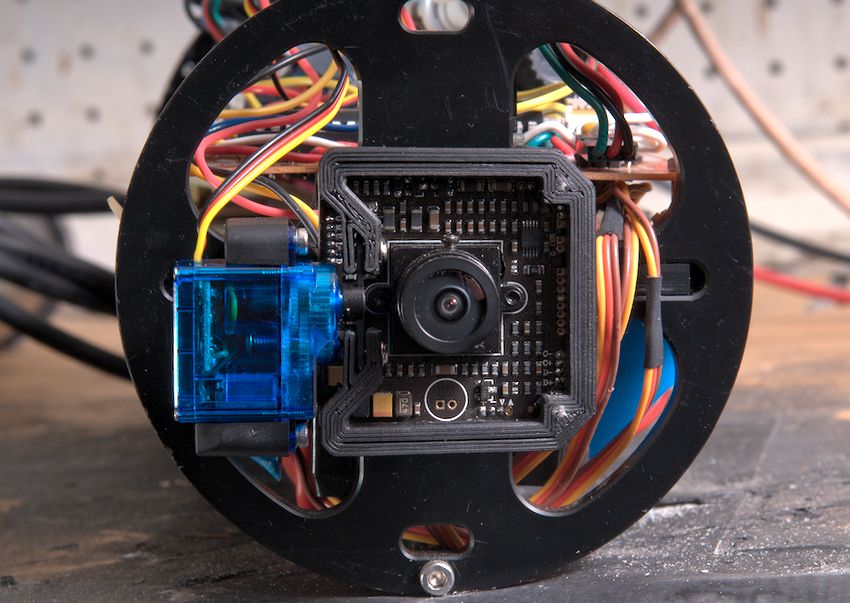
A servo mounted analog camera sits at the front of the housing and sends the video signal topside through one of the twisted pairs of the CAT5 tether. A PWM signal from the ROV MCU controls the servo position. This particular camera is the low-light analog module sold on the Blue Robotics website. (Although it appears that they have end-of-life/discontinued it.) The servo motor will have to be purchased separately as well.
That is the general concept behind the physical aspects of my ROV circuit. Next up we will begin to look at the microcontroller code for the ROV vehicle.