The next significant addition to the ROV is that of a robotic gripper arm. The goal was to have the ability to extend and retract a set of mechanical jaws, tilt them up and down and of course open/close the jaws themselves. We will start with the construction of the arm itself followed by the circuitry behind it it. Lastly, in the next page we will explore the software controlling the movement of the arm
Arm Construction
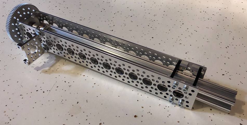
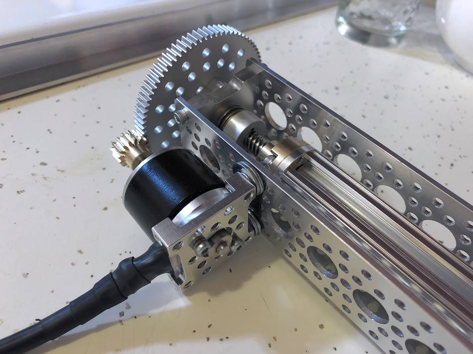
The basis of the gripper arm is an aluminum Linear actuator kit sold by Servocity. The kit comes with the chanel, rail, sliders, lead screw, motor mount, two spur gears and fastening hardware. Depending on the physical dimensions of the motor you are using (as well as its rotational speed), you may need to get a different mount and gear set. Since I didn't want to drive the lead screw too fast, I opted for a larger diameter 84 tooth/32 pitch hub-mounted gear combined with a smaller 16 tooth/32 pitch pinion gear mounted to the shaft of the motor. This combination gives an approximate 5:1 gear reduction and allowed for more fine-tuned control over extending/retracting of the lead screw (compared to the 1:1 ratio you would get with the kit-supplied gears). Below we see the constructed assembly with the 84 tooth hub-mounted gear (minus the motor):
Lead screw motor
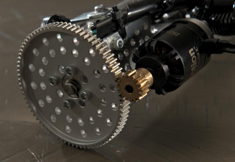
The initial brushless motor used to drive the lead screw was the Blue Robotics M100. It was a logical choice due to its ideal size for the application combined with its low KV rating (RPM/V) as well as the fact that it was waterproofed/potted from the factory. It is also the same motor that powers the 6 T100 thrusters on the ROV. In the photos below you can see this motor with the above mentioned pinion gear mounted in place:
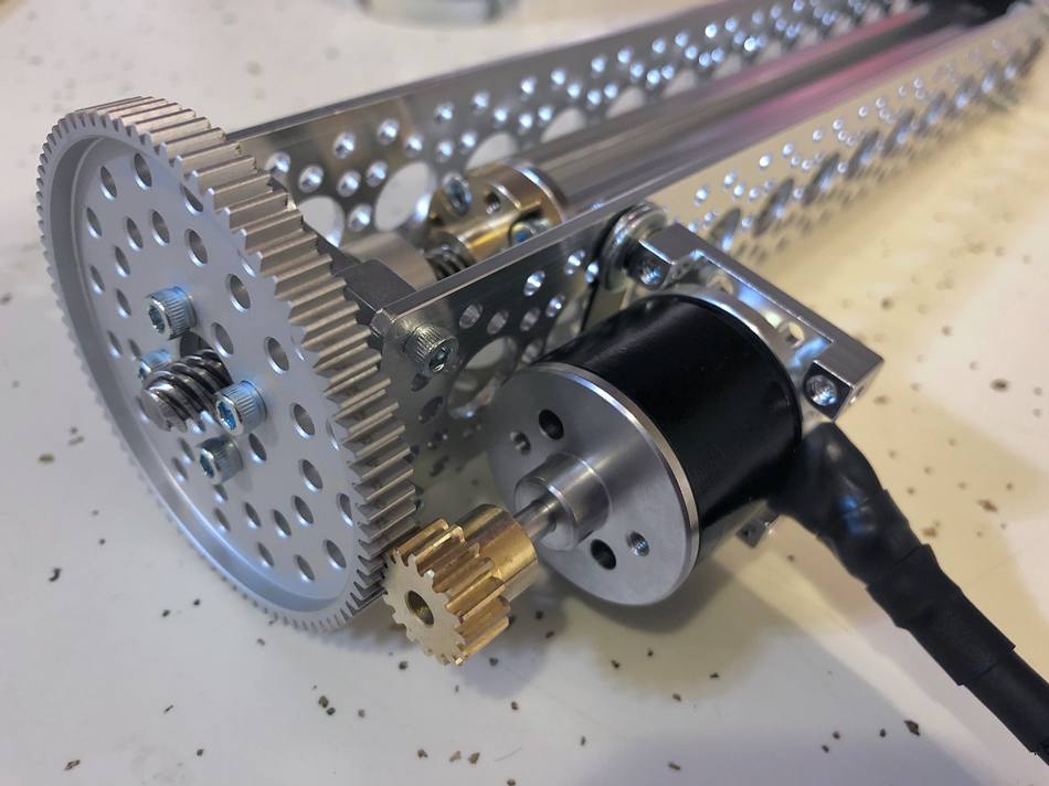
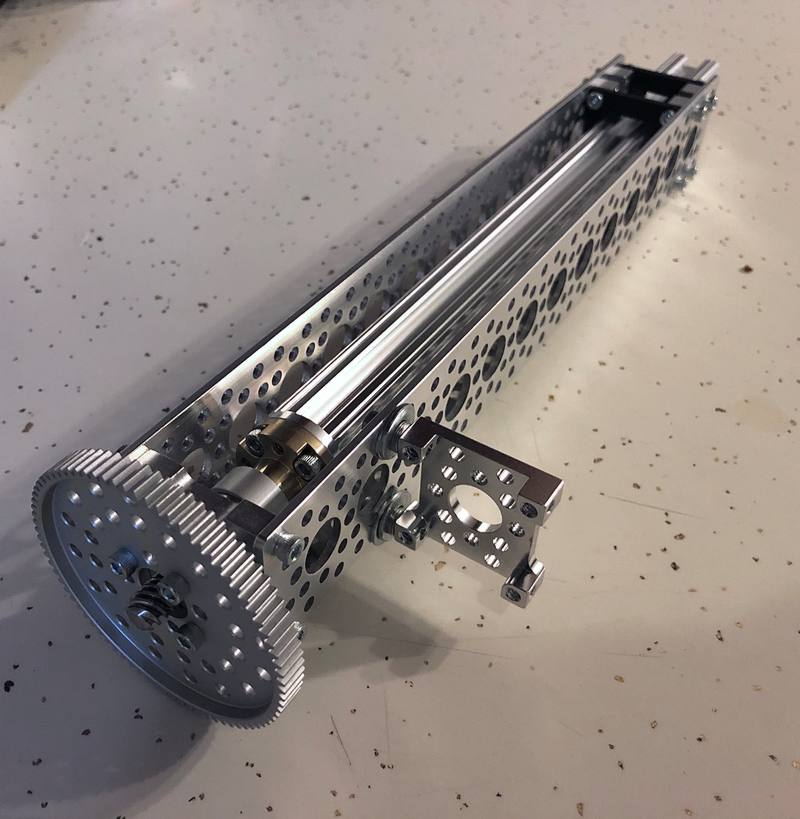
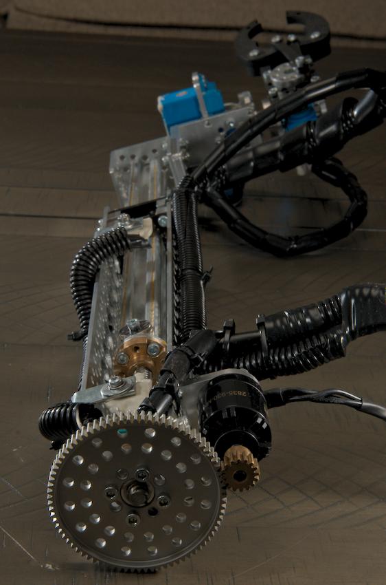
Unfortunately, Blue Robotics discontinued this motor (as well as the T100 thruster). Not wanting to design the mechanism around an irreplaceable part right from the start, I opted for a motor sold by Lynxmotion that can found here. While it has a slightly higher KV rating, the form factor is right and the price is reasonable. The downside is that the motor is not waterproof and I had to pot the windings in thermally-conductive epoxy (perhaps material for another tutorial). Additionally, the bearings will be prone to rust and while I have an alternative method of dealing with this, I have not yet implemented it. The photos below shows the setup with this particular motor mounted to the channel of the kit:
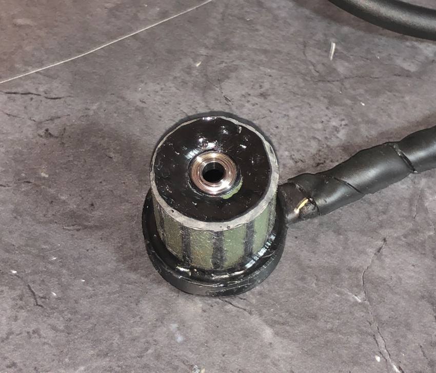
The epoxy-potted windings of the motor can be seen below:
Additionally, the motor is driven by the same style ESC that is used for the 6 thruster motors.
Limit switches
Limit switches are utilized to prevent damage to the motor, gears or structure of the arm due to driving the lead screw past its intended range of motion. Specifically, these limit switches use hall-effect sensors and a magnet. These particular hall-effect sensors are normally in the "high" position (5V) and drop low (0V) in the prescence of a magnetic field. The low signal occurs when the magnet mounted to the sliding rail of the gripper arm reaches the hall-effect sensors at the extreme ends of travel. The outputs of the sensors are fed to the microcontroller found on the gripper arm control board. If the controller sees a low signal coming from either sensor, it stops the lead screw motor and will only allow it to be driven in the opposite direction. I designed a small and simple PCB to hold the hall-effect sensor, pull-up resistor and wire connections. A mounting hole was included in the PCB for attaching it to the channel of the actuator kit. The board is shown below (minus the components):
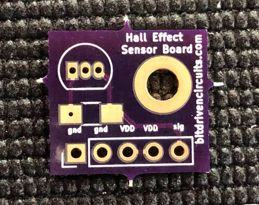
(The schematic for this board can be found here.)
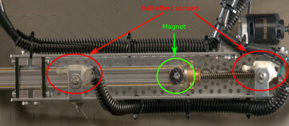
The limit switch assemblies were then potted in marine epoxy and mounted to the channel of the linear actuator mechanism. A neodymium magnet was also attached to the sliding portion of the arm (as seen below:)
Below are two brief videos demonstrating the lead screw being driven to the limits of its intended range of motion (max-retracted and max-extended) and being halted by the limit switches once these extremes are met. These videos were taken during the prototype phase:
Gripper Mechanism
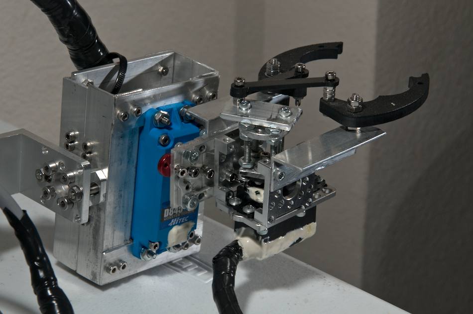
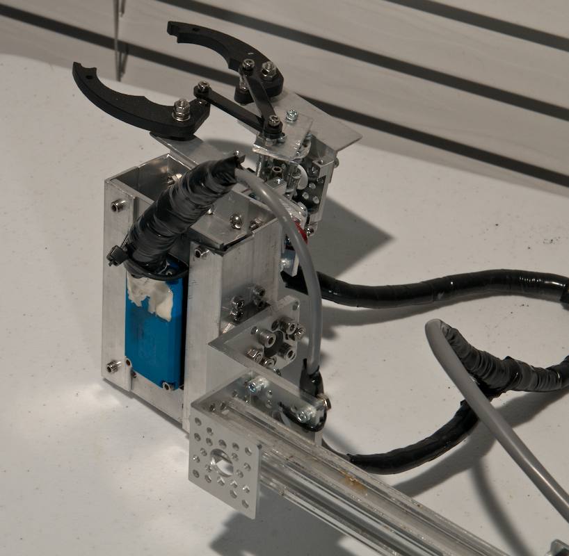
The gripper mechanism itself has two functions: 1) Tilt up and down 2) Open and close the jaws. This is done via two servos arranged in a configuration shown below:
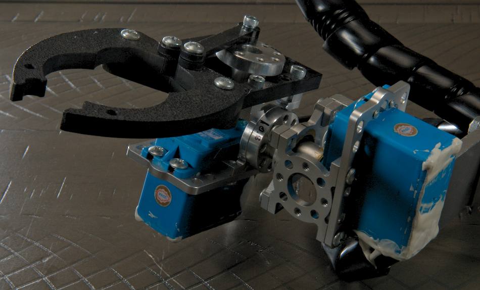
The gripper kit was purchased from Servocity and can be found here. The servos used in the original design are Hitech HS-646WP models. Unfortunately, the plastic frame for the gripper jaws cracked in two places. Rather than order an new one, I decided to fabricate a crude (but more robust) frame out of aluminum angle stock. Additionally, I upgraded the HS-646WP servo that controlled the tilting action to a larger, higher torque Hitec model D845WP. The original HS-646WP servo that controls the jaws also failed during testing (due to abuse) and I replaced it with an inexpensive unit of similar form-factor from Amazon (can't remember the name/model). This current configuration is shown in the photos below:
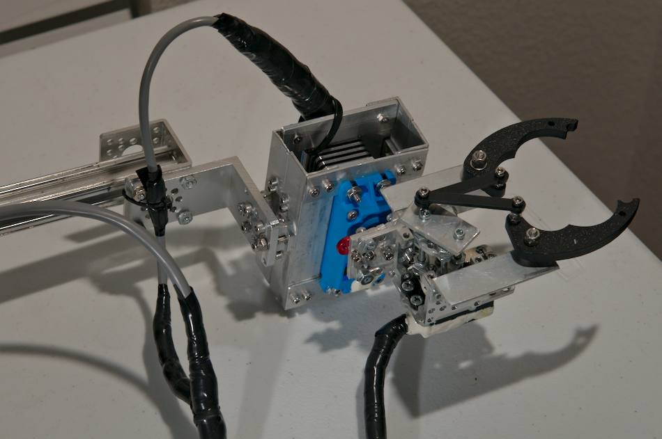
While the Hitech servos are advertised as being "waterproof", they are in fact only water resistant and not designed to be submerged at any significant depth. With this in mind, I filled each servo with mineral oil (to help deter any pressurized ingress of water) and used a combination of RTV liquid gasket (as well as marine epoxy) to seal the cases of the servos. The mineral oil is non-conductive in nature and does not require any electrical contacts inside the servo be insulated.
Control Board
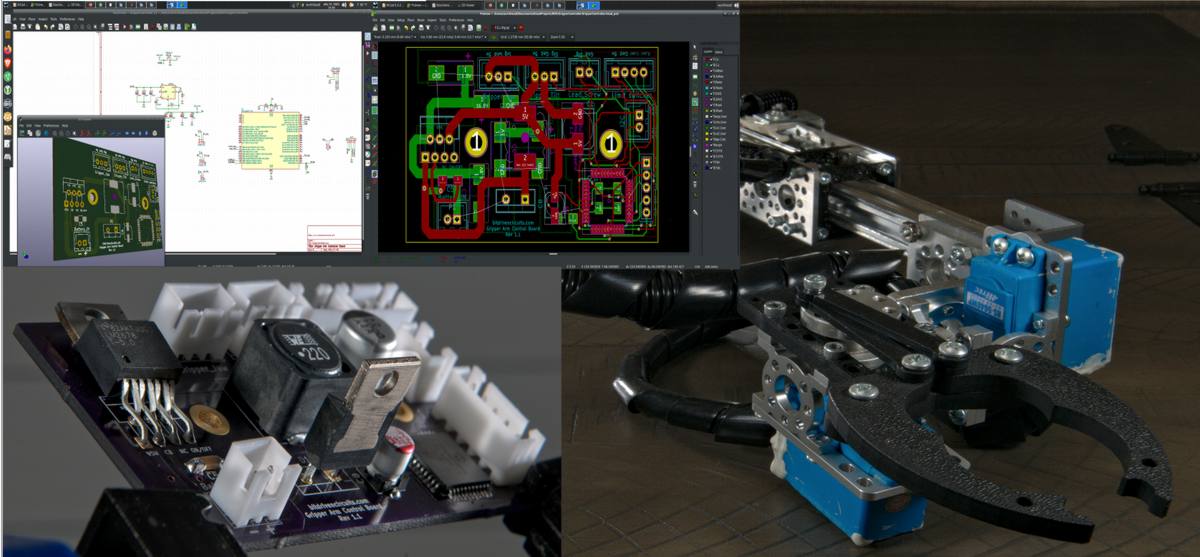
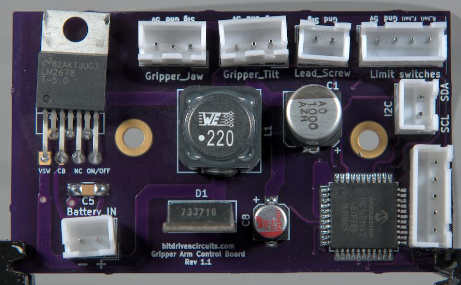
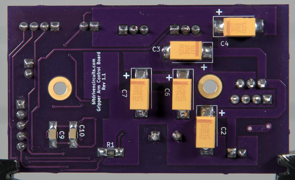
The control board for the gripper arm is based around a Microchip PIC16F1937. It receives commands from the main control board of the ROV (via the I2C protocol) and translates these commands into PWM signals to be sent to the brushless motor ESC and gripper tilt/jaw servos. The board contains a Texas Instruments LM2678 5V/5A switching regulator which takes the ROV battery as an input and supplies 5V to the board as well as the two servos. The board also has a 4-pin header for supplying 5V to the limit switches and taking their signals as inputs. Lastly, there is a 5 pin connector for ICSP (In Circuit Serial Programming) which allows for firmware updates via a Microchip PICKIT2, 3 or 4. The connectors used are all JST-XH. The photos below show the front and back sides of the gripper arm control board:
The PCB design and layout was done by myself in Kicad and the bare (unpopulated) board was fabricated by Oshpark. The schematic for the design is shown below:
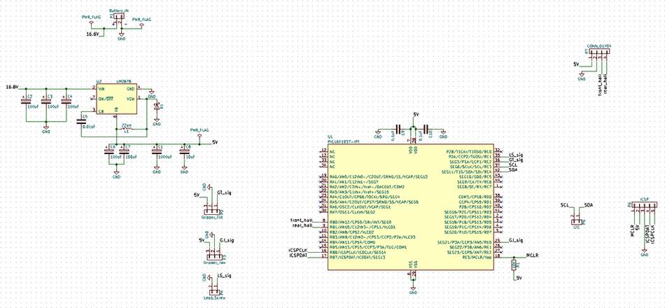
A high-res version of the schematic can be found here.
Next up we will look at the software used to control the gripper arm.
Continue on to ROV (part 7/gripper arm software)...