In this page we will discuss how the ROV sends the individual battery cell voltage readings to the control box on the surface. We will not discuss operation of the Battery Monitoring Circuit (BMC) itself since this is discussed in a separate section of the website. For more information take a look at the LiPo Battery Monitor documentation.
The frequency with which the battery cells are read is determined by surface control box. Once the control box determines it needs to retrieve battery voltage information from the ROV, a call is made to the subroutine called "BatteryVoltage" (found in the uart.asm file). This subroutine starts off by sending the defined command for a battery reading to the ROV (d'255'). Upon receiving the command, the ROV then retrieves the voltage levels from the battery monitoring circuit (BMC) via the i2c protocol. This process is explained the the i2c communication section of the BMC documentation.
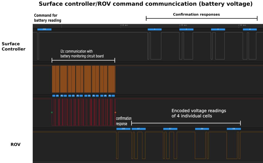
The control box then waits for the ROV to acknowledge the command and proceeds to receive the voltage data for the four individual cells of the LiPo battery. After the transmission of each packet, the ROV waits for confirmation of reception by the control box before sending the next packet in sequence.
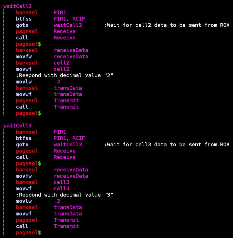
Using battery cells 2 and 3 as examples, the code below shows how th control box both receives the data and confirms its reception:
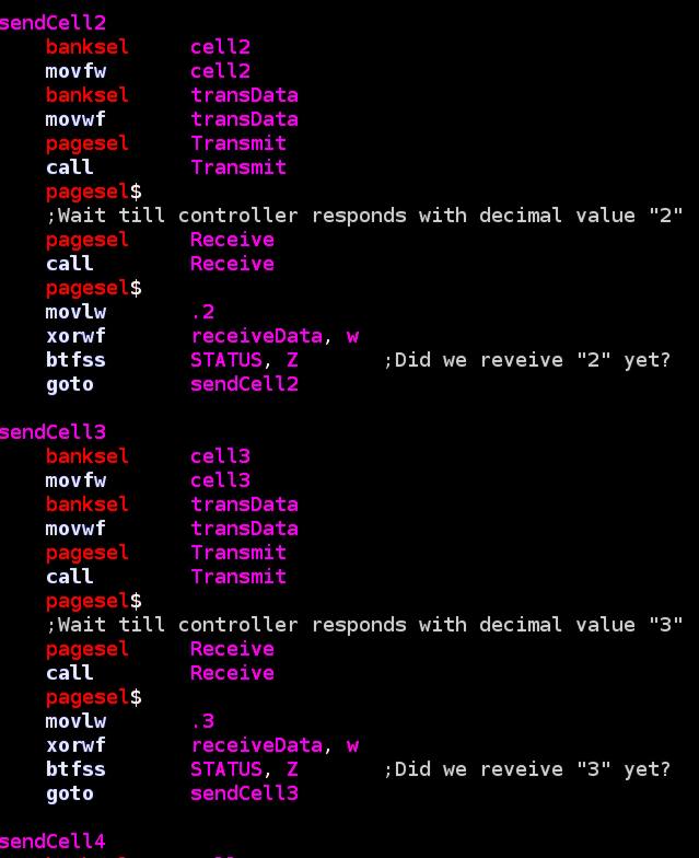
...and below is the corresponding code used by the ROV to send the battery data for cells 2 and 3 and wait for confirmation of reception by the surface controller:
Below we revisit the logic analyzer capture that shows this communication scheme between the control box and the ROV:
Control Box processes battery cell data
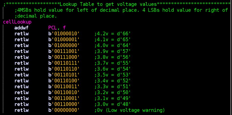
When the BMC reads the voltage levels of the four LiPo cells, it encodes them into an 8-bit number that can represent a range of values from 3.0-4.2 V (min-max values of each cell). The method of encoding is to let the 4 most significant bits (4 msb) represent the voltage value to the left of the decimal point (this will be a "3" or "4") and the 4 least significant bits (4 lsb) represent the voltage value to the right of the decimal point (from "0" to "9"). The screen shot of the lookup-table inside the BMC program file demonstrates this:
Let's take a look at a logic analyzer capture of the communication between the ROV and BMC:
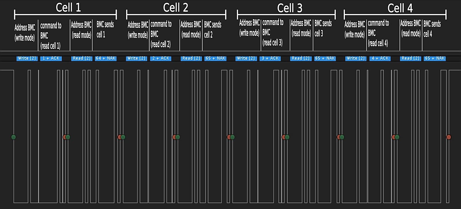
If you examine the logic analyzer capture above, you see that cell 1 is encoded as decimal number "64" (4.0V) and cells 2,3, and 4 are encoded as decimal number "65" (4.1V). For example, if we examine cell #3's encoded value (decimal number "65"), we see that:
- d'65' = b'01000001'
- 4 most significant bytes = b'0100' = d'4'
- 4 least significant bytes = b'0001' = d'1'
- Encoded cell voltage for cell #3 = 4.1V
After receiving and storing these battery cell readings, the control box must then display them on the LCD screen. This is done by making a call to the subroutine "VoltageUpdate" (found in the LCD.asm file).
In the next section we will examine the LED lights used on the ROV.
Continue on to ROV (part 5/Lights)...