
So now that our control box device has sent the data stream to the ROV, we need to figure out a way to process and decode those packets in a manner to causes the vehicle to respond to the intent of the operator. Everything in the ROV microcontroller program is interrupt driven. The configuration of the PIC peripherals/modules is similar to that found on the control box device, so I won't repeat the explanation here. Before we begin receiving and decoding signals, we first need to initialize the 6 thruster ESCs.
Microcontroller and ESC Initialization
Upon device startup, the peripherals are initialized. The 6 ESCs connected to the thruster motors are also initialized by sending them a stopped signal (1.5mS pulse-width) for four seconds. It should be noted that ESC initialization needs to take place AFTER configuring the PWM module since PWM signals are used as part of the initialization process.
Interrupts
Interrupts are triggered by UART receptions. An interrupt triggered by the UART module can be one of three things:
- A packet that is part of the normal data stream
- A command to perform a battery voltage reading
- A command to perform a temperature reading
Determining which one of these three things caused the interrupt is the job of the interrupt service routine (ISR) and is done at the start of the ISR (after context variables have been saved):
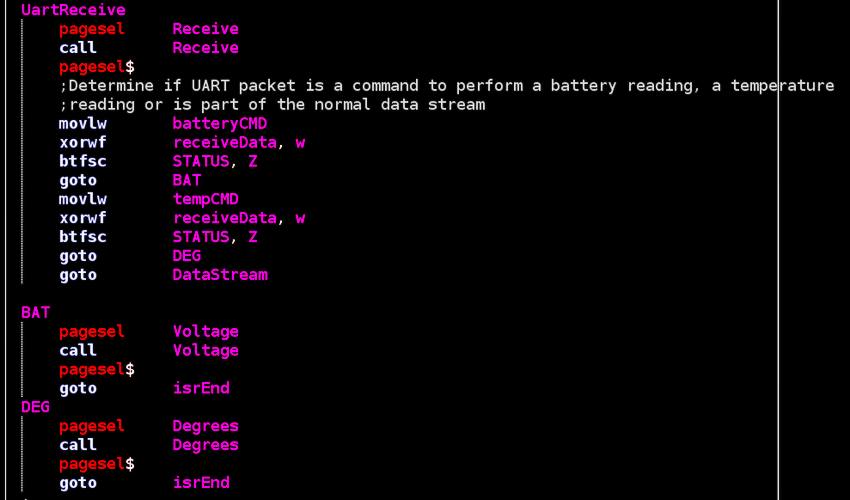
The ISR is found in the main.asm file.
If the data packet is found to be a command for either a battery or temperature reading, the appropriate subroutine is called. The subroutines for voltage readings and temperature readings are found in the battery.asm and ms5837.asm files respectively. Both routines make use of the i2c serial protocol to communicate with the battery monitoring circuit board and the temperature sensor.
If the UART packet is part of the normal data stream, then the ISR checks the state of a counter (named "UartReceiveCtr") and processes the packet accordingly. "UartReceiveCtr" is incremented after every data-stream packet reception and is reset when a "state" data packet is sent (to keep everything in order). Depending one the purpose of the packet being received, another subroutine is called to process it. These subroutines can be found in the motorStuff.asm file. Below we see the subroutine called to process the forward directional speed of the thrusters:
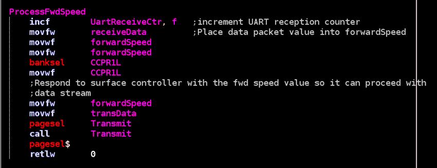
The screen shot above also shows the confirmation reply sent to the surface controller letting it know to proceed with the data stream communication. Below we see the processing of the data packet that controls the opening/closing of gripper jaws:
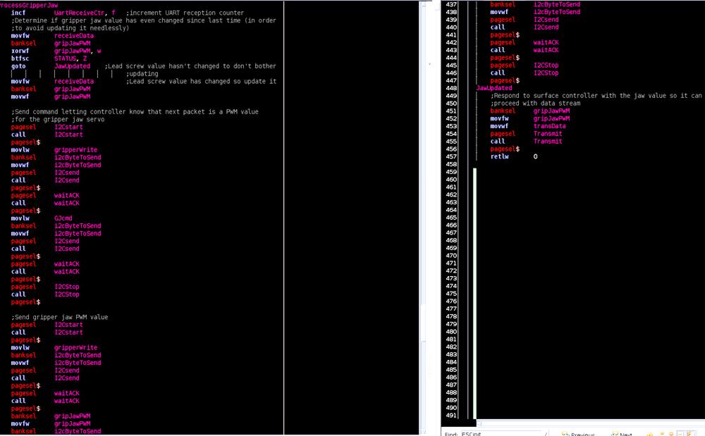
In the above screen shot we see how the i2c protocol is used to communicate with the gripper control board.
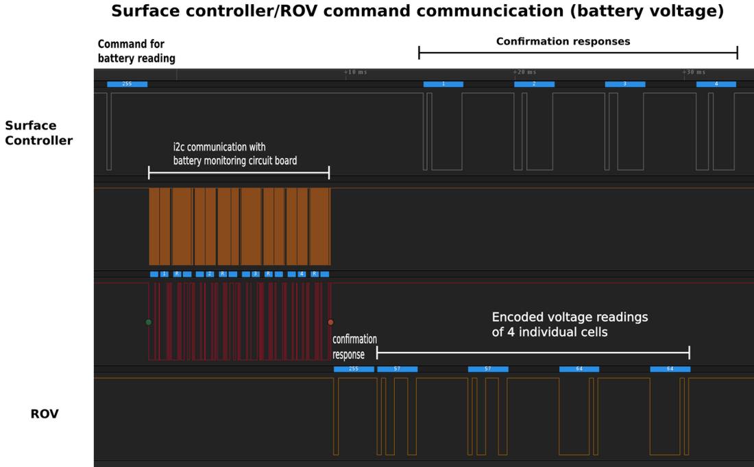
This process is continually repeated and used to process all data packets sent by the surface controller. Additionally, UART interrupts are disabled during the processing of data packets so as to not cause problems during the confirmation "handshakes" that happen during packet transmission. Below we see the logic analyzer screen capture (with added labels) displaying the communication sequence between the surface controller and ROV:

Below we see the logic analyzer capture during the communication of a command to perform a battery voltage reading:
In the next section we will take a look at the considerations/concerns behind battery selection for poweringthe ROV.