
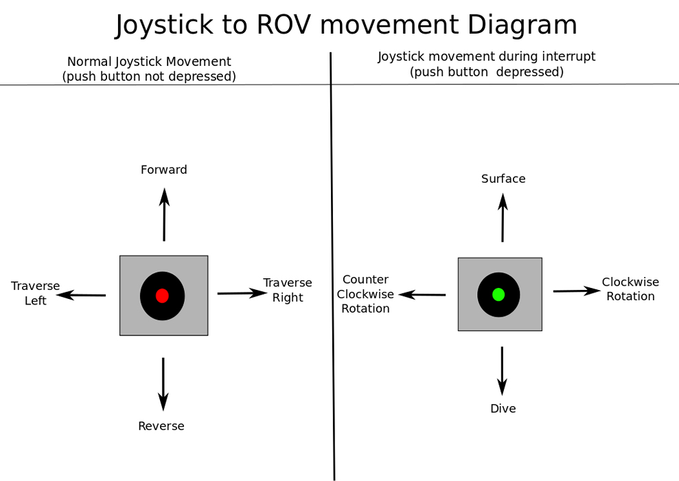
As was mentioned earlier, the rotational and vertical movement of our ROV will controlled via an interrupt that is triggered upon pressing the momentarily-closed push button switch found on the handle of the joystick. To help us to better understand how the directional movement of the joystick translates to directional movement of the ROV, consider the following diagram:
The interrupt service routine can be found in the main.asm file. Once the source of the interrupt is determined, the appropriate subroutine is called in response to which PORTB input caused the interrupt. These subroutines are found in the interrupts.asm file. Aside from the joystick push-button switch, a change in position of the gain-selector switch will also trigger an interrupt. After saving away our context variables, we determine the interrupt source with the following code:
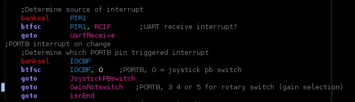
Once the source of the interrupt is determined, the appropriate sub-routine is called. These routines can be found in the interrupts.asm file.
Configuring the MCU for Interrupt
Now that we understand the general idea of what the interrupt is doing, let's take a look at how to configure our MCU so that it will trigger an interrupt upon the pushing of the joystick switch. This configuration (along with all of the MCU configuring) can be found in the init.asm file. In our case, the joystick PB-switch as well as the three inputs from the rotary (gain-selection) switch will be connected to PORTB. PORTB, 1 and PORTB, 2 are outputs for the 4480 LCD. I configure the PORTB register as follows:
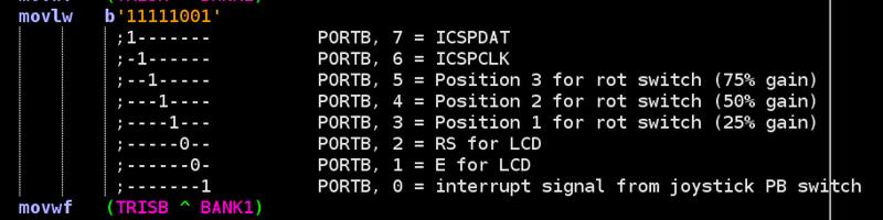
You will notice that PORTB 6 and 7 are configured for i2c serial communication. This feature is not currently being used with the control box, but I have plans for it in the future.
Peripheral, global and PORTB interrupts are enabled by setting the following bits in the INTCON and IOCB registers as seen below:
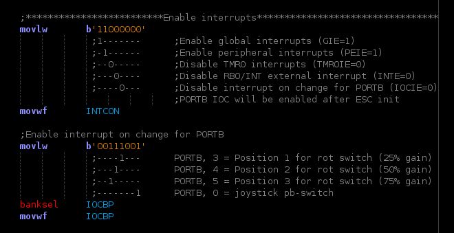
Notice that while INTCON, IOCIE is disabled here (for PORTB interrupt on change), it is enabled after initialization is complete and the handshake has been completed between the control box and ROV.
With all of the above completed, we have now effectively set up an interrupt service routine to handle rotational and vertical movement of our ROV. We will revisit the topic of interrupts when we discuss serial communication and the use of the UART module for both the control box and sub-surface vehicle.