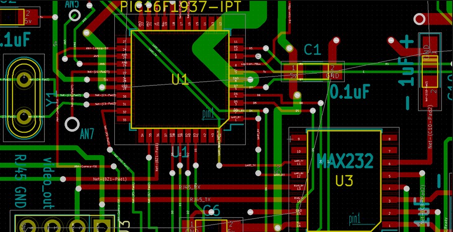
The time has now come to send the results of our previous calculations to the underwater ROV. The method by which we will do so is through the use of the PIC's UART module. This module uses to RS232 serial protocol to both send and receive data between devices. It is an asynchronous protocol and therefore does not require the use of a synchronizing clock.
Configuring the UART module
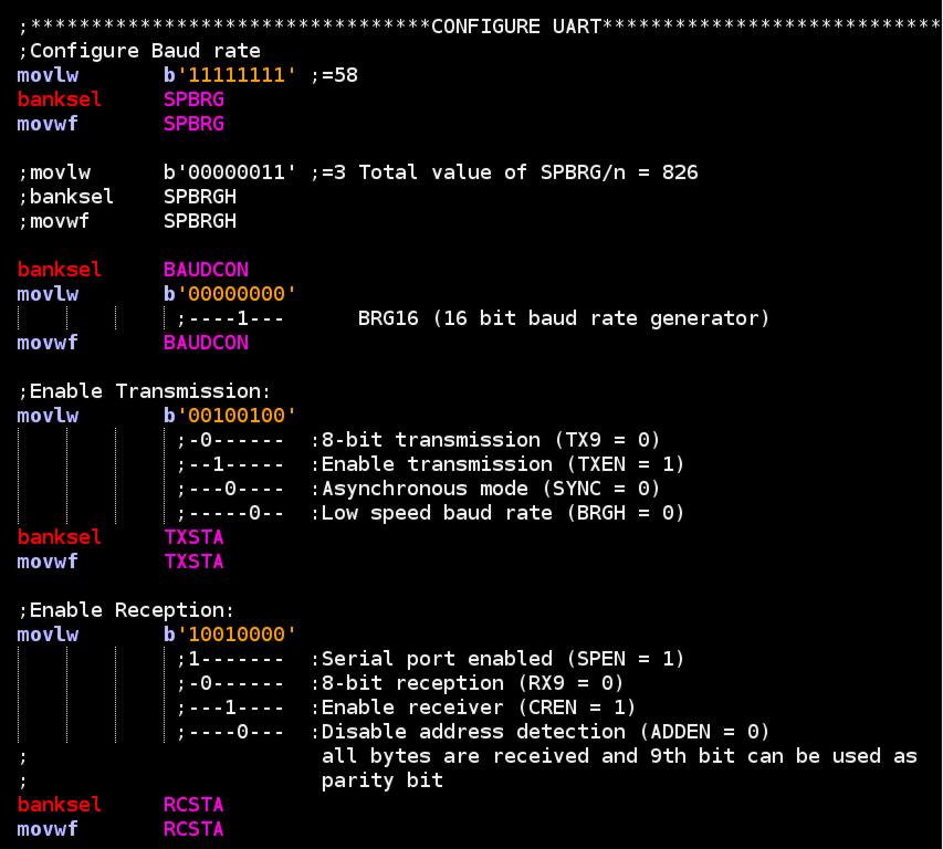
We begin by configuring the UART module for both transmission and reception as well as set the baud rate with the code below (Which is found in the init.asm file.)
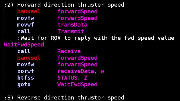
With the UART module configured, we are now able to use it to send data packets to the ROV. After the various values for the data packets have been calculated, the subroutine "sendThrust" is called. Inside the "sendThrust" routine, the gain adjustments are also applied to the thruster data. The "sendThrust" subroutine can be found in the uart.asm file. For each individual packet transmission, the value is sent to the ROV and the ROV is expected to reply with the same value. If the control box does not receive a matching response from the ROV it will continue to send the packet until it does. Below we see the code for this technique with the "forwardSpeed" data packet:
For each packet transmission, the data is placed into a variable/memory location named "transData" just before calling the subroutine "Transmit". The "Transmit" routine is also found in the uart.asm file and is also shown below:
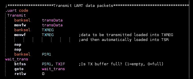
Once "transData" is loaded into TXREG, it is automatically shifted into the TSR register by the hardware and then pushed out onto the UART transmit pin (labeled TX/pin #25). The packet is now effectively on it's way to the ROV. Before exiting the "Transmit" subroutine, we poll the TXIF flag of the PIR1 register. As long as this bit is set, there is still data in the buffer waiting to be shifted out. If we were to exit the routine and send more data before the buffer was empty, packet corruption would result. Once the flag is clear, we exit this "wait_trans" loop and then exit the subroutine.
Counters and Commands:
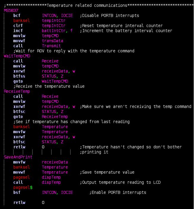
As the ROV receives these packets, it increments a counter to keep track of the intended purpose behind the data contained in each packet. Additionally, the control box makes use of two counters that set the interval for retrieving temperature and battery data from the ROV. At the bottom of the program's main loop, these counters are checked. If the pre-determined interval has been met for a temperature or battery voltage reading, the corresponding subroutines are called. These subroutines are called "MS5837" (found in uart.asm) and "BatteryVoltage" (also found in uart.asm). When these two subroutines are called, specific commands are sent to the ROV. The ROV receives these commands and uses the i2c protocol to retrieve data from either the temperature sensor or battery monitoring circuit. This data is then sent to the control box. As an example, we see the subroutine "MS5837" below:
Once the control box receives the data, it then displays any relevant information on the 20x4 LCD. Additionally, the control box also communicates with the ROV and determines the status of the on-board leak detector. If a leak is detected, the ROV communicates this to the control box and the user is alerted to a leak condition via a message on the LCD (as well as a buzzer alarm and LED).
Summary
So with all of the above accomplished, we have more or less configured our control box MCU to:
- Perform multiple AD conversions from the joysticks and knobs.
- Convert the results from the AD conversions to values to be utilized by the ROV microcontroller.
- Send these results to the ROV via UART.
- Receive any data packets from the ROV via UART.
Next we will begin to discuss the LCD panel and the various messages it displays.